The gpi port, Overview, Isolated connection – XTA DC1048 User Manual
Page 40
Page 40
DC1048 Integrated Audio Management
Operator’s Manual
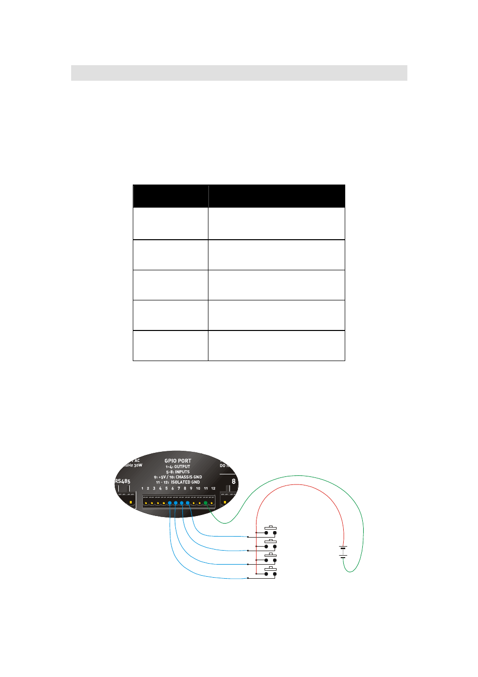
Isolated connection.
Connect external supply to
between common on switches, and
pin 11 ground only.
Momentary Action
Switch (Mem #01)
+9volts
The GPI Port
Overview
The GPI port is designed for connection to either isolated or non-isolated systems
to facilitate remote memory recalls without the need of a computer. There are
three modes of operation, as defined in the GPI Menu > GPI
GPI
GPI
GPI via the front panel.
These are explained in the next few pages, but first the difference between
isolated and non-isolated connections.
Pin Number
Description
1 – 4
Outputs
Connect to WP-1048 only
5 - 8
Inputs
(0V – off; 2.5V – 10V max = on)
9
Output – +5V
(current limited to 200mA)
10
Output – Chassis Ground
(connect for non-isolated use)
11 - 12
Output – Isolated Ground
(connect only for isolated use)
Isolated Connection
Pin 11 is internally connected to the common cathodes of the opto-isolators and
so to trigger them, this must be joined to the negative side of any external
supply. Chassis ground is NOT connected, nor is the available +5v supply on pin
9. Instead, an external power source provides a voltage, which is switched as
necessary onto the anodes of the opto-isolators triggering memory recalls.