Vectored interrupt cycle timing, Figure 101 – Zilog Z86193 User Manual
Page 114
Z8
®
CPU
User Manual
UM001604-0108
Interrupts
107
Vectored Interrupt Cycle Timing
The interrupt acknowledge cycle time is 24 internal clock cycles and is displayed in
on page 108. In addition, two internal clock cycles are required for the syn-
chronizing flip-flops. The maximum interrupt recognition time is equal to the number of
clock cycles required for the longest executing instruction present in the user program
(assumes worst case condition of interrupt sampling,
on page 99, just prior to
the interrupt occurrence). To calculate the worst case interrupt latency (maximum time
required from interrupt generation to fetch of the first instruction of the interrupt service
routine), sum these components:
Worst Case Interrupt Latency
≈
24 INT CLK (interrupt acknowledge time) + # T
P
C of
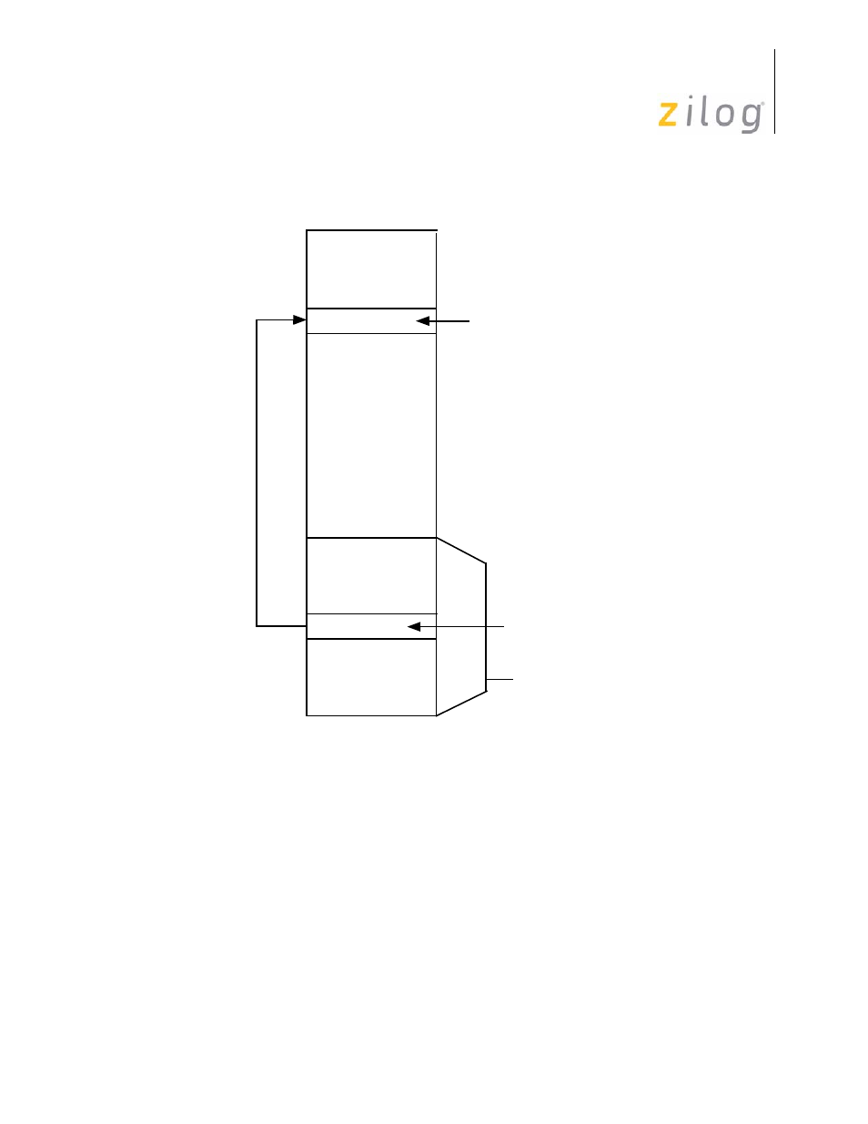
Figure 101. Interrupt Vectoring
PC HIGH Byte
FLAGS
Vector Selected
000Ch
Program Memory
Interrupt
Service
Routine
By Priority Logic
Interrupt
Vector Table
0000h
XXFFh