Back panel diagram – Adtec digital mediaHUB (version 02.00.13) User Manual
Page 9
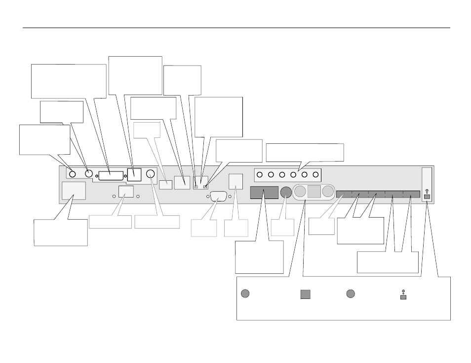
Ethernet
10/100 Base T Ethernet.
Connect to PC for
access to the adCode
application from the
same network.
Terminal
Serial port typically
used for diagnostics.
Ethernet
Busy LED -
Illuminates when
Ethernet activity
occurs - yellow
Ethernet
Link LED - Illuminates
when connected to a
network
Ethernet
Link LED - Illuminates
when connected to a
network - green
IEEE 1394
Not Used
Audio Out 5.1
Left - Right - Center - L Surr - R Surr - Sub
Stereo:
Unbalanced
analog stereo audio
out (1/8” female)
DVI-I OUT:
Digital Video Interface
(DVI-I) supports both digital
(DVI-D) and analog (DVI-A) outputs
for VGA and Component (RGB/YUV)
with an optional cable. Refer to
Appendix E for pinout specifications.
S-Video OUT:
7-Pin
Media Port for Video out
configurable to
Composite (BNC), or
S-Video (4-pin mini-din
Y/C). Cable required for
VGA, YUV and RGB.
Encoder RS422
Connect to media
source. Must be Sony
protocol tape deck
interface.
LTC
Not Used
RS232
Not Used
USB 2.0
Not Used
Gigabit Ethernet
Not Used
CBVS-Out:
Reserved
for future use.
C IN
(Lowest Quality)
Composite IN Video Source
YC IN
( Mid Quality)
S Video Source
SDI IN
(Broadcast Quality)
Serial Digital Input
Video and embedded
AES audio source.
Firewire
(Professional Quality)
DV25 IEEE 1394
Video and audio
source.
Power - AC Line Input
Standard 3 pin computer
power plug. ( Auto range
70-240 VAC Input )
GP IO
Not Used
AES Audio (OUT/IN)
Digital audio
compressed or
uncompressed inputs
1
2
Audio Channels IN
Analog balanced audio input.
Stereo pairs (ch1 & ch2)
1
2
SPDIF:
Digital audio
(RCA) configurable as
Compressed (for 5.1
AC-3 audio) or
Uncompressed (PCM 2
channel).
Back Panel Diagram
Figure 1.2