3. starting the v-scale plus – Analog Way V-Scale C - VSL300 User Manual
Page 17
VSL range
Chapter 2 : STARTING (continued)
PAGE 17
2-3. STARTING THE V-SCALE PLUS
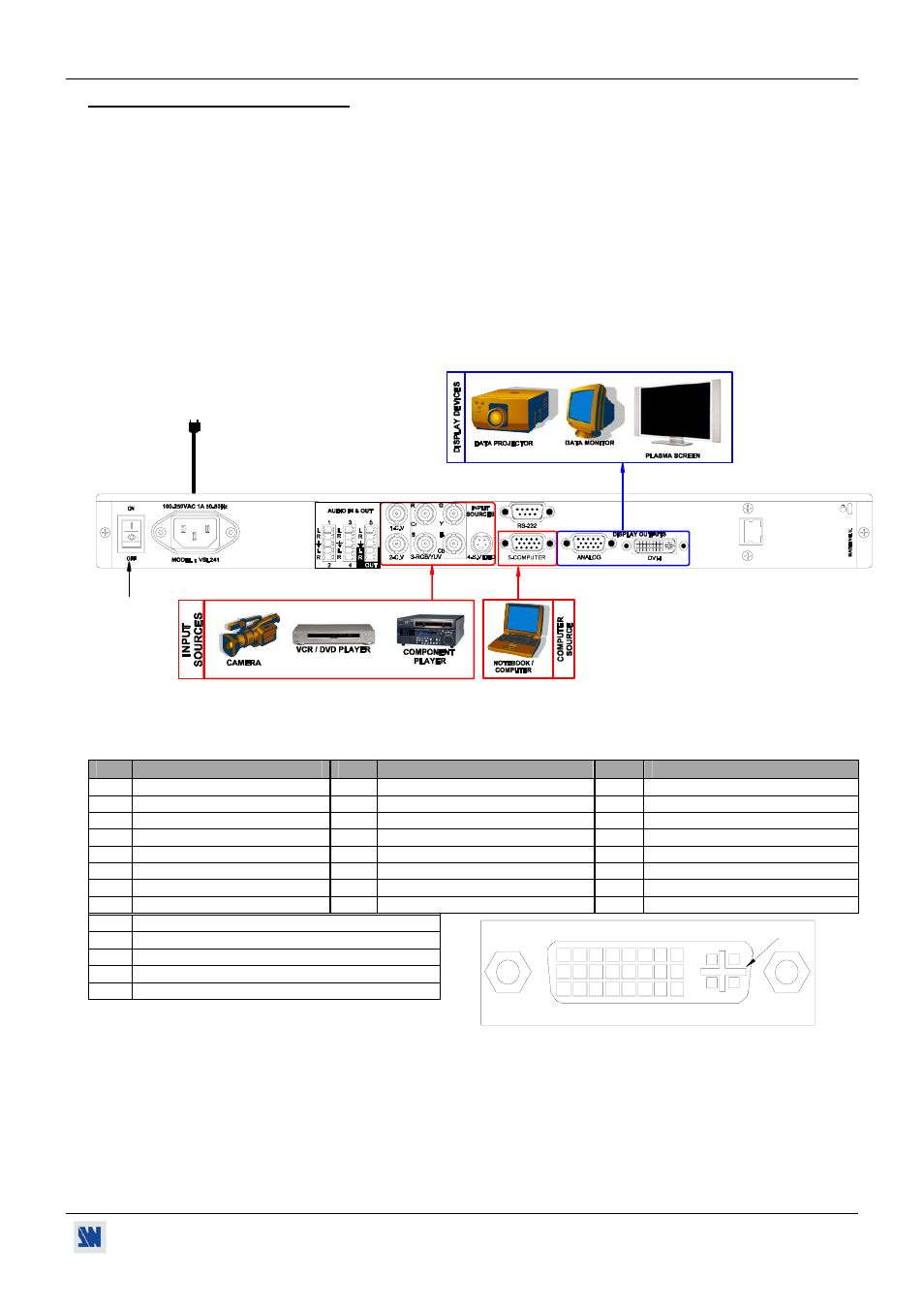
• Connections:
c Turn OFF all of your equipment before connecting.
d Connect your video sources to the inputs 1, 2, 3 & 4 of the V-SCALE PLUS.
e Connect your computer source to the input 5 of the V-SCALE PLUS.
f Connect your display device (projector, plasma screen...) to the DISPLAY OUTPUTS (HD15 or DVI-I female
connectors) of the V-SCALE PLUS.
g Connect the AC power supply cord to the V-SCALE PLUS and to an AC power outlet.
h Turn ON the V-SCALE PLUS (rear panel switch). Then turn ON all your input sources and then your display
device.
• V-SCALE PLUS connection diagram:
IP/L
A
N
3
2
4
6
5
• DVI-I pin assignment:
The DVI-I female connector of the V-SCALE PLUS can be used with digital signals as well as analog signals. The table
hereafter explain the pin assignment of these connectors.
Pin
Function
Pin
Function
Pin
Function
1
TMDS Data 2-
9
TMDS Data 1-
17
TMDS Data 0-
2
TMDS Data 2+
10
TMDS Data 1+
18
TMDS Data 0+
3
TMDS Data 2 Shield
11
TMDS Data 1 Shield
19
TMDS Data 0 Shield
4
Not used.
12
Not used.
20
Not used.
5
Not used.
13
Not used.
21
Not used.
6
DDC Clock
14
+ 5V (Power)
22
TMDS Clock Shield
7
DDC Data
15
Ground for (+5V)
23
TMDS Clock+
8
Analog Vertical Sync.
16
Hot plug detect.
24
TMDS Clock-
C1
Analog Red video
C2
Analog Green Video
C3
Analog Bleu Video
C4
Analog Horizontal Sync
C5
Analog Common Ground Return
DDC = Display Data Channel.
TMDS = Transition Minimized Differential Signal.
8
1
9
16
24
17
C1 C2
C3 C4
C5