Using the wordclock input, Figure 5 - wordclock connections – ART Pro Audio TubeOpto 8 - Eight Ch. Mic Preamp with ADAT User Manual
Page 10
Using the Wordclock input
The Tubeopto 8™ can be used in both simple and complex systems. The simplest system would consist of
the Tubeopto 8™ and a single ADAT interface. As multiple digital devices are added to a system, master/slave
sample rate timing issues can degrade system audio performance. Using a single master wordclock to
synchronize all of the digital processing units reduces timing offset, and eliminates effects from any time drift
between the units thereby improving audio quality and reliability. When Wordclock is used it should to be
applied to EVERY unit in the digital audio chain including soundcards.
First, assure that the Tubeopto 8™ is connected to a good Wordclock generator running at the intended
sample rate.
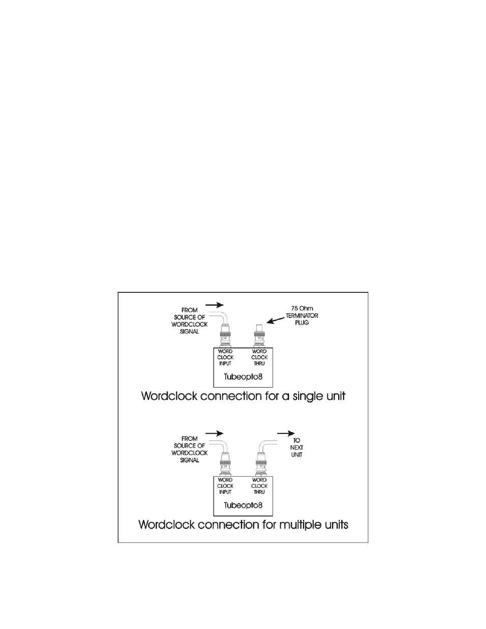
Multiple Tubeopto 8™ units can be daisy-chained by looping the wordclock signal from unit to unit using the
Wordclock Input and Thru jacks of each Tubeopto 8™. A single 75 Ohm BNC terminator is placed on the
Wordclock Thru jack of the last device in the chain (furthest away from the wordclock generator).
Alternatively multiple Tubeopto 8™ units can be connected directly to the separate outputs of a wordclock
generator in which case each Tubeopto 8™ will require a 75-Ohm BNC terminator placed on its respective
Wordclock Thru jack. (Because the Tubeopto 8™ is not an internally terminated device.)
Next, click the Sample Rate button until the display shows “Wordclock”.
(If the Wordclock LED is flashing, check to make sure that the cables are connected correctly and the
incoming wordclock is between 40KHz and 52KHz.)
The Tubeopto 8™ is now slaved to the external Wordclock generator along with the other units in the
system.
FIGURE 5 - Wordclock Connections
7