Sample rate leds, Power switch, Rear panel – ART Pro Audio TubeOpto 8 - Eight Ch. Mic Preamp with ADAT User Manual
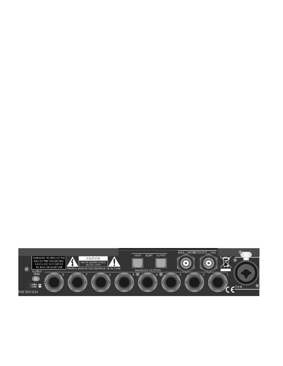
Page 7: Balanced input jacks – xlr & 1/4” trs combo jacks, Balanced output jacks, Output level switch, Figure 3 - rear panel
Sample Rate LEDs
This display indicates the rate and source of the A/D converter sample rate. (The D/A sample rate is
independent of this setting as it always slaves to the incoming ADAT data).
The ADAT LED will flash if there is no incoming ADAT data, or a data error. This is true for every sample rate
mode (not just ADAT).
Selecting Wordclock will light the red Wordclock LED and this LED will flash if the Tubeopto 8™ cannot use
this input as a sync source. This LED will only flash if Wordclock mode is selected.
Power Switch
This switch controls and indicates that the unit is powered up and operational. When dimly lit, it indicates a
low power source or an internal problem.
REAR PANEL
Balanced Input Jacks – XLR & 1/4” TRS Combo Jacks
These balanced inputs are used for both microphone and line level signals. The gain sensitivity is identical for
both the XLR and 1/4” TRS jacks, however the XLR input impedance is 6.4K Ohms and the 1/4” TRS input
impedance is 20K Ohms. The front panel Pad switch varies the sensitivity of both inputs.
Balanced Output Jacks
Eight low impedance 1/4” TRS balanced output jacks provide audio output from the D/A converters driven by
the ADAT Lightpipe Input.
Output Level Switch
This switch optimizes the output level of the rear output jacks with your system operating level. Depress the
switch when connected to +4dB systems. In this case the maximum output is +20dBu when the digital level
equals 0 VU.
When the switch is in the “out” position, the output levels are optimized for –10dBV systems.
FIGURE 3 - Rear Panel
4