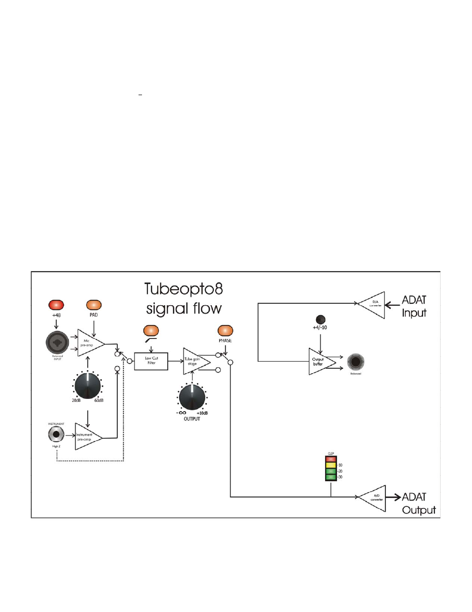
Wordclock input and thru jacks, Adat lightpipe jacks, Figure 4 - block diagram – ART Pro Audio TubeOpto 8 - Eight Ch. Mic Preamp with ADAT User Manual
Page 8: Adat jacks
Wordclock Input and Thru Jacks
The Wordclock input is used to externally sync the Tubeopto 8™ to a master clock source. The BNC
Wordclock Input jack is connected directly to the BNC Wordclock Thru jack, providing the ability to loop
through the Tubeopto 8™ and connect other devices to the wordclock sync source, saving the use of a BNC
T–adapter.
FIGURE 4 - Block Diagram The Wordclock input is high impedance thus leaving the wordclock connection
unterminated. (A 75 Ohm BNC terminator should be used on the Wordclock Thru jack if the Wordclock Input
jack is used only.)
ADAT Lightpipe Jacks
Each ADAT Lightpipe jack supports eight channels of 24 bit digital audio data conforming to the ADAT
Lightpipe protocol, which transfers eight tracks over a single fiber optic cable. Sample rates of 44.1KHz and
48KHz are supported by this standard.
The ADAT Lightpipe Output jack data is generated by the eight internal A/D converters that are directly driven
by the outputs of the eight preamplifier channels. The A/D sample rate and sync source are selected by the
front panel switch.
The ADAT Lightpipe Input jack accepts eight channels of digital audio data at any sample rate between
40KHz and 52KHz. This data is directed thru the eight internal D/A converters to the eight rear balanced audio
outputs. The front panel Sample Rate switch DOES NOT affect this input. Since the D/A converters sample
rate is derived from whatever is coming in the ADAT Input jack, this section can lock to non-standard sample
rates as long as they are between 40KHz and 52KHz.
FIGURE 4 - Block Diagram
5