Table 6-23, Logical device primary interrupt register, Table 6-24 – Artesyn ATCA 7370 / ATCA 7370-S Installation and Use (January 2015) User Manual
Page 131: Logical device 0x74 reserved register, Maps and registers
Maps and Registers
ATCA-7370/ATCA-7370-S Installation and Use (6806800P54H)
131
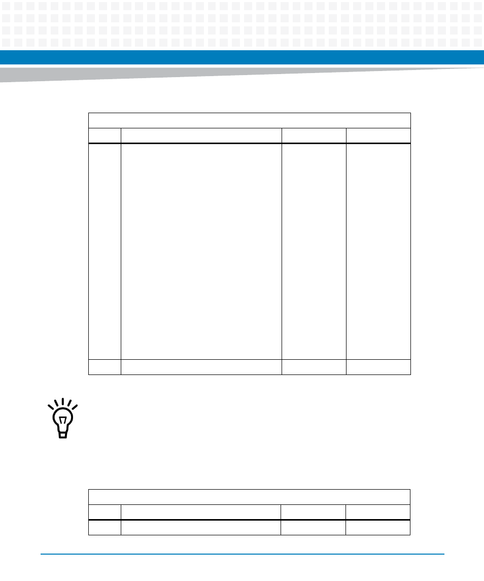
Table 6-23 Logical Device Primary Interrupt Register
Index Address: 0x70
Bit
Description
Default
Access
3:0
Interrupt level is used for Primary Interrupt:
0x0: no interrupt selected
0x1: IRQ1
0x2: IRQ2
0x3: IRQ3
0x4: IRQ4
0x5: IRQ5
0x6: IRQ6
0x7: IRQ7
0x8: IRQ8
0x9: IRQ9
0xA: IRQ10
0xB: IRQ11
0xC: IRQ12
0xD: IRQ13
0xE: IRQ14
0xF: IRQ15
0
LPC: r/w
7:4
Reserved
0
LPC: r
An Interrupt is activated by enabling this device (offset 0x30), setting this register to a non-
zero value and setting any combination of bits 0-4 in the corresponding UART IER and the
occurrence of the corresponding UART event (i.e. Modem Status Change, Receiver Line Error
Condition, Transmit Data Request, Receiver Data Available or Receiver Time Out) and setting
the OUT2 bit in the MCR.
Table 6-24 Logical Device 0x74 Reserved Register
Index Address: 0x74
Bit
Description
Default
Access
7:0
Reserved
0x04
LPC: r