Table 3-3, Amc module ethernet interface connector pinout, Figure 3-5 – Artesyn ATCA-F120 Installation and Use (August 2014) User Manual
Page 55: Controls, leds and connectors
Advertising
Controls, LEDs and Connectors
ATCA-F120 Installation and Use (6806800D06J)
55
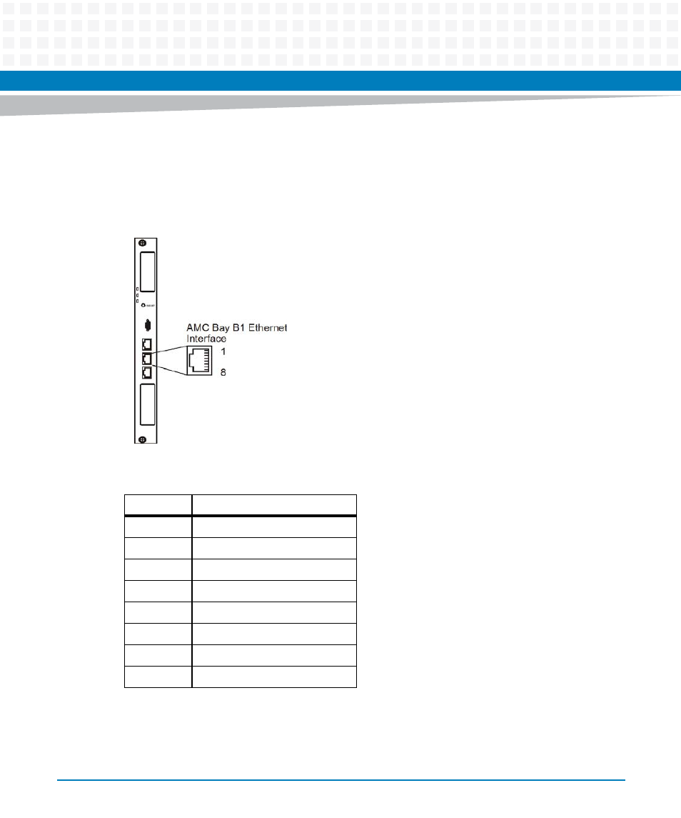
The following figure shows the connector location and pinout.
Figure 3-5
Location of AMC Module Ethernet Management Interface Connector
Table 3-3 AMC Module Ethernet Interface Connector Pinout
Pin
Signal (1000Base-T)
1
ETH_DA+
2
ETH_DA-
3
ETH_DB+
4
ETH_DC+
5
ETH_DC-
6
ETH_DB-
7
ETH_DD+
8
ETH_DD-
Advertising