Table 1-2, Mvme761 transition module connectors, Table 1-3 – Artesyn MVME7616E Transition Module Installation and Use (April 2015) User Manual
Page 18: Row p2 adapter connectors (mvme761-001), Table 1-4, Row p2 adapter connectors (mvme761-011), General information
General Information
MVME7616E Transition Module Installation and Use (6806800A43D)
18
1. You will need to purchase or fabricate the port cables.
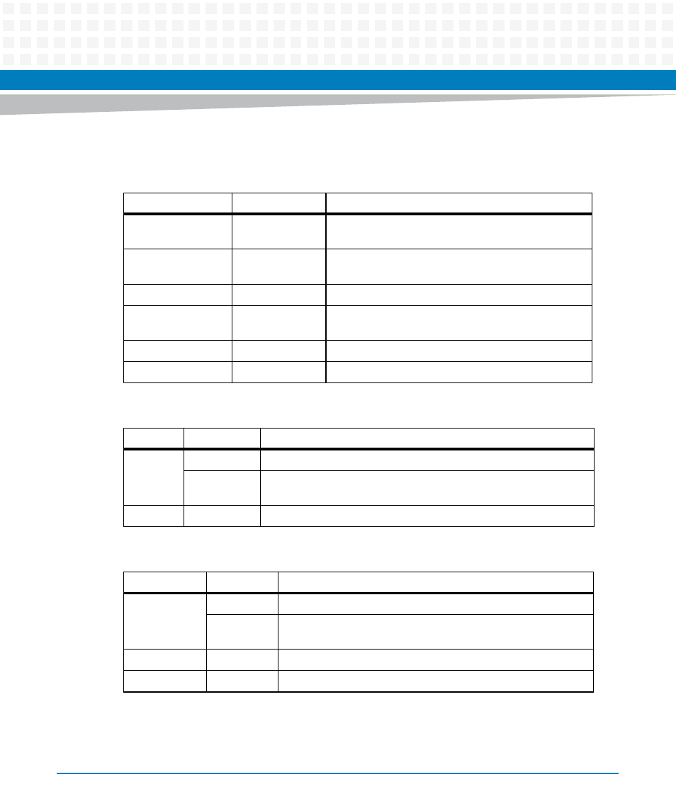
Table 1-2 MVME761 Transition Module Connectors
Type
Number
Description
COM1 and
COM2
J5
J6
9-pin male DIN asynchronous serial port connector
Serial port 3
Serial port 4
J7
J8
26-pin female HD-26 synchronous serial port
connector
Parallel port
J4
36-pin female parallel port connector
10Base-T,
100Base-TX
J9
8-pin female RJ-45 Ethernet port connector
SIM
J1, J12
60-pin female connector
VME
P2
64-pin male connector to J2 on the P2 adapter
Table 1-3 3-Row P2 Adapter Connectors (MVME761-001)
Type
Number
Description
VME
P1
96-pin female DIN 41612 connector to the chassis backplane
J3
64-pin male connector for output to P2 on the MVME761 transition
module
SCSI
J2
50-pin male IDC connector for internal SCSI devices
Table 1-4 5-Row P2 Adapter Connectors (MVME761-011)
Type
Number
Description
VME
P1
160-pin female DIN 41612 connector to the chassis backplane
J4
64-pin male connector for output to P2 on the MVME761
transition module
PMC I/O
J3
64-pin male connector for PMC I/O
SCSI
J1
68-pin female IDC connector for internal SCSI devices