Hardware preparation and installation, 1 overview, 2 unpacking the hardware – Artesyn MVME7616E Transition Module Installation and Use (April 2015) User Manual
Page 21: 3 installing the serial interface modules, Figure 2-1, Serial port interface jumper setting, Chapter 2
Chapter 2
MVME7616E Transition Module Installation and Use (6806800A43D)
21
Hardware Preparation and Installation
2.1
Overview
This chapter provides unpacking instructions, hardware preparation, and installation
instructions for the MVME761 transition module, the P2 adapter, and the Serial Interface
Modules (SIMs).
2.2
Unpacking the Hardware
The MVME761 is packed in an antistatic wrapper to protect it from static discharge. Artesyn
strongly recommends that you use an antistatic wrist strap and a conductive foam pad when
handling the equipment. Electronic components can be extremely sensitive to electrostatic
discharge (ESD). After removing the board from the protective wrapper, place it component
side up on a grounded, static-free surface. Do not slide the board over any surface.
Unpack the equipment from the shipping carton. Refer to the packing list and verify that all the
items are present. Save the packing material for storing and reshipping of the equipment.
2.3
Installing the Serial Interface Modules
Configure the serial ports 3 and 4 for the required interface by installing the appropriate SIM.
See
for a list of the serial port interface types.
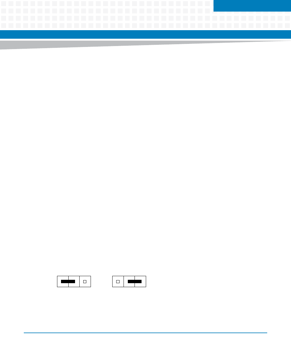
Prior to installing the SIMs, set the jumpers on header J2 (for serial port 3) and header J3 (for
serial port 4) for either DCE or DTE. Set the jumper to position:
1-2 if the SIM is for a DTE interface
2-3 if the SIM is for a DCE
Figure 2-1
Serial Port Interface Jumper Setting
1
2
3
1
2
3
DCE
DTE