General, Mounting, Section 4 – Basler Electric BE1-50/51B-232 User Manual
Page 31: Installation -1, General -1, Mounting -1
SECTION 4
INSTALLATION
GENERAL
When not shipped as part of a control or switchgear panel, the relays are shipped in sturdy cartons to
prevent damage during transit. Immediately upon receipt of a relay, check the model and part number
against the requisition and packing list to see that they agree. Visually inspect the relay for damage that
may have occurred during shipment. If there is evidence of damage, immediately file a claim with the
carrier and notify the Regional Sales Office, or contact the Sales Representative at Basler Electric,
Highland, Illinois.
Proper operation of the relay may be confirmed by performing the operational test procedure of Section 5.
If the relay won't be installed immediately, store the relay in its original shipping carton in a moisture and
dust-free environment.
MOUNTING
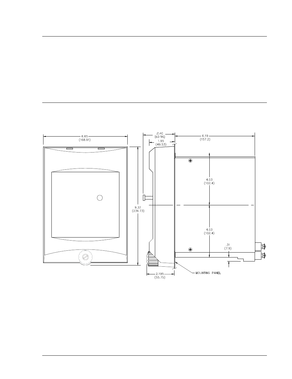
Relay outline dimensions and panel drilling diagrams are shown in Figures 4-1 through 4-4. Dimensions
in parentheses are in millimeters.
D2750-29
Figure 4-1. Outline Dimensions for S1 Case, Semi-Flush Mounting
9252000896 Rev B
BE1-50/51B-232 Installation
4-1