Controls and indicators, Introduction, Section 2 • controls and indicators -1 – Basler Electric BE1-59N User Manual
Page 17: Introduction -1
SECTION 2 • CONTROLS AND INDICATORS
INTRODUCTION
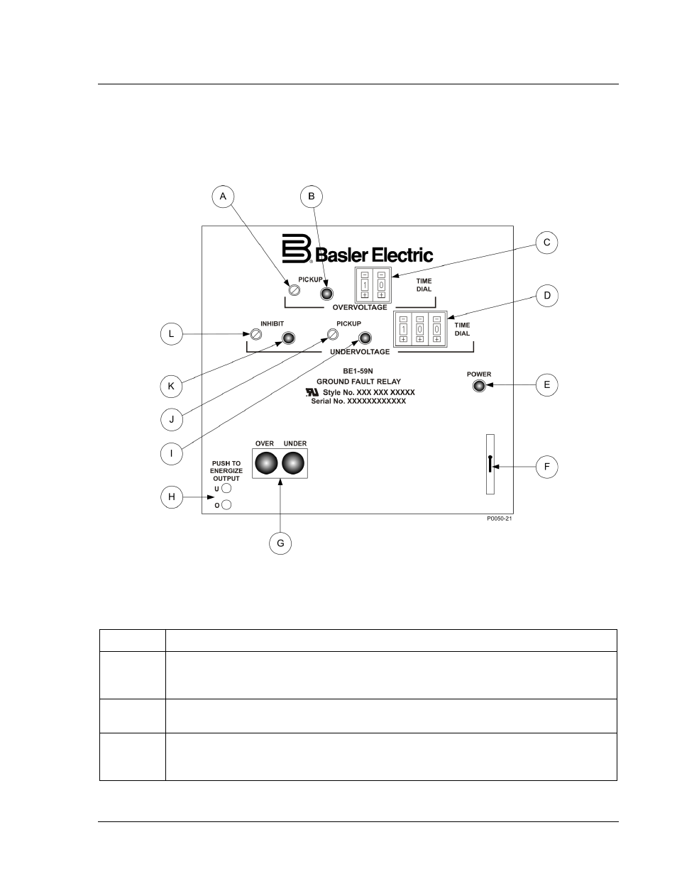
All BE1-59N controls and indicators are located on the front panel. The controls and indicators are shown
in Figure 2-1 and described in Table 2-1. Figure 2-1 illustrates a relay with the maximum number of
controls and indicators. Your relay may not have all of the controls and indicators shown and described
here.
Figure 2-1. BE1-59N Controls and Indicators
Table 2-1. Control and Indicator Descriptions
Locator
Description
A
Overvoltage Pickup Adjustment. A multiturn potentiometer that sets the overvoltage
comparator threshold voltage. Continuously adjustable over the range indicated by the
style chart.
B
Overvoltage Pickup LED. A red LED that illuminates when overvoltage exceeds the
pickup setting.
C
Overvoltage Time Dial. Pushbutton switch that selects the desired overvoltage output
delay, either definite time (from 00.1 to 99.9 seconds) or, inverse time (characteristic
curves 01 through 99). A setting of 00 is instantaneous in either case.
9171400990 Rev K
BE1-59N Controls and Indicators
2-1