Signal, Connector description, Power supply – BECKHOFF C9900-A172 User Manual
Page 11: Usb data transfer, Usb output, Dvi output (digital visual interface), Dvi data transfer
Product Description
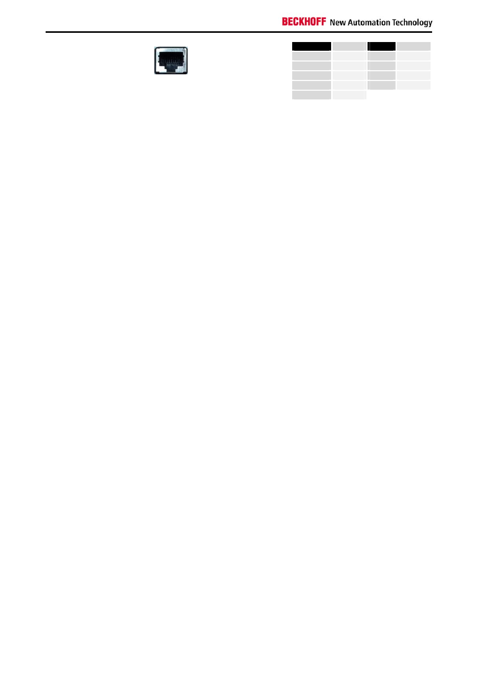
Pin
Signal
Pin
Signal
Housing
Screen
5
n.c.
1
TD +
6
RD -
2
TD -
7
n.c.
3
RD +
8
n.c.
X 104
DVI Extension
RJ-45 connector (Ethernet 10/ 100 Mbit)
4
n.c.
Connector description
Power supply
Power supply
The power supply for the Control Panel is established via the Cage clamp
socket (X 100).
USB data transfer
USB Extension
The USB extension connection (X 101) is used for transferring the USB
signal from the transmitter module to the receiver module.
USB output
USB Downstream
The USB1.1 input (X 102) is used to connect the receiver module with the
Control Panel.
USB1.1 standard with a maximum data rate of 1.5 or 12 Mbps is
supported.
DVI output (Digital Visual Interface)
DVI-D Out
The DVI connection (X 103) is used for transferring the video signal from
the receiver module to the Control Panel.
The purely digital part (DVI-D) is supported.
DVI data transfer
DVI Extension
The DVI extension connection (X 104) is used for transferring the DVI
signal from the transmitter module to the receiver module.
10
DVI/USB extension C9900-A17x