Beisler 739-23-1 Service Manual User Manual
Page 5
2.2
Description of integrated adjusting screw
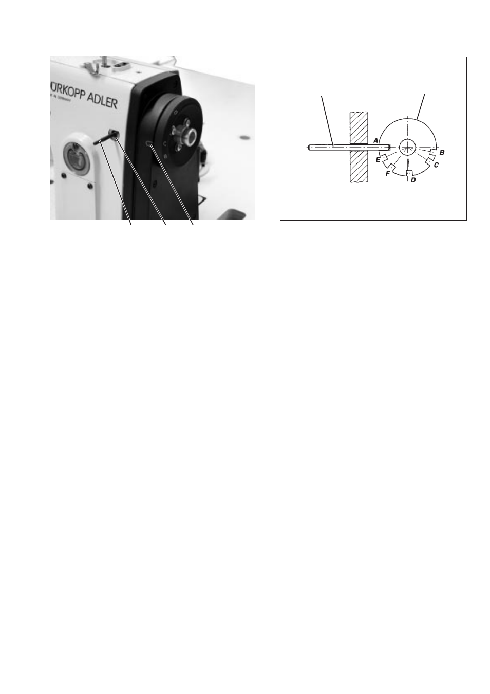
By means of the retention pin 3 and the adjusting disc 4 integrated in
the toothed belt wheel, the sewing machine can be locked in the
current setting positions.
The adjusting disc is equipped with 6 recesses that are labeled on the
hand wheel as A, B, C, D, E and F. In connection with the mark 1, the
letters indicate the position of the recesses at which the machine can
be locked by means of pin 3.
Recess A (loop stroke position) is deeper than the other recesses.
To adjust the individual positions, proceed as follows:
A
Adjusting disc to groove in the arm shaft crank,
loop stroke, distance of hook tip to needle.
B
not yet assigned !
C
Thread lever up
D
not yet assigned !
E
Height of needle bar
F
not yet assigned !
3-5
4
3
3
2
1