Beisler 739-23-1 Service Manual User Manual
Page 6
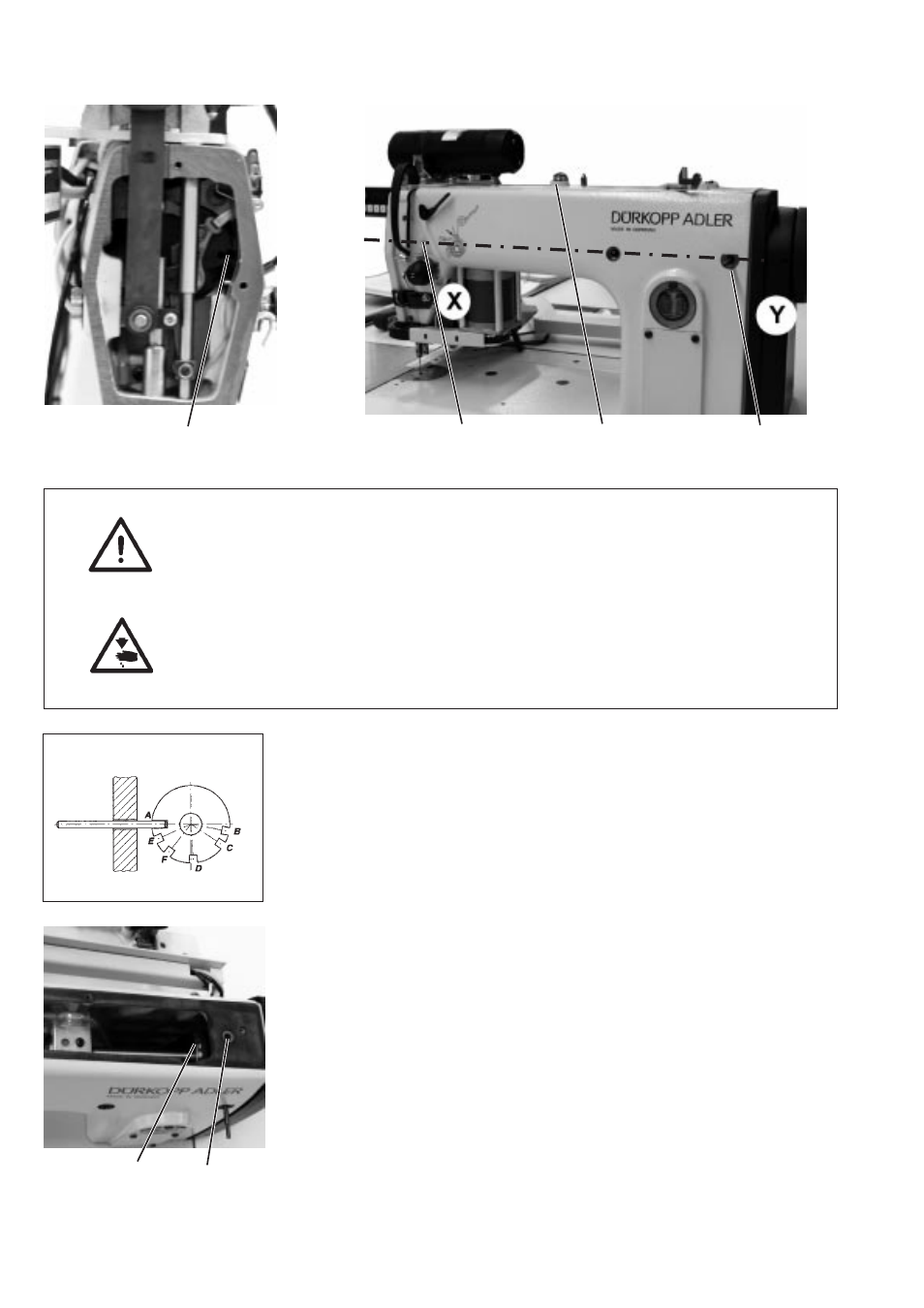
2.3
Position of integrated adjusting disc to arm shaft crank
CAUTION!
All adjustments carried out by means of the adjusting disc are only
correct, if the adjusting disc is set as described in these instructions. If
the arm shaft is moved, the following settings and position must be
inspected and corrected, if necessary.
Caution! Risk of injury!
Switch off main switch !
Check and correct the position of the adjusting disc only when the
sewing machine is
switched off.
Instruction and inspection
The groove 4 and the cut A of the adjusting disc integrated in the
toothed belt wheel must be aligned to line X - Y.
–
Lock arm shaft with a retention pin or a Ø 5 mm pin placed in the
arm shaft groove 4 (through hole 3).
–
It must be possible to insert the retention pin through hole 1 in
hand wheel position A into the integrated adjusting disc.
Adjustment
–
Remove bobbin cover 2.
–
Pull toothed belt from belt wheel.
–
Loosen screws of belt wheel 6.
Insert hexagon socket key from the top through hole 5.
–
Lock belt wheel with retention pin in position A.
–
Insert a 5 mm Ø pin into positioning hole 3 and ensure that the pin
is engaged at the arm shaft groove 4.
–
Retighten screws on belt wheel 6.
The belt wheel may thereby not be moved in axial direction.
–
Pull toothed belt onto the belt wheel.
3-6
3
2
1
4
6
5