Communication interfaces, Serial interface – Bematech KF-6580 User Manual
Page 16
User’s Manual
16
Figure 16
25
.............
24
.............
23
.............
22
.............
21
.............
20
.............
19
.............
18
.............
17
.............
16
.............
.................
13
.................
12
.................
11
.................
10
.................
09
.................
08
.................
07
.................
06
.................
05
.................
04
.................
03
Printer Side (DB-25)
Host Side (DB-25)
2 (TD)
3 (RD)
3 (RD)
2 (TD)
6 (DSR)
20 (DTR)
7 (GND)
7 (GND)
20 (DTR)
6 (DSR)
4-5-8 (jumper)
Communication between a host and the printer can be performed in three communication protocols: USB, Parallel
or Serial RS-232, according to the printer model.
Communication cables are not supplied with the printer
Serial Interface
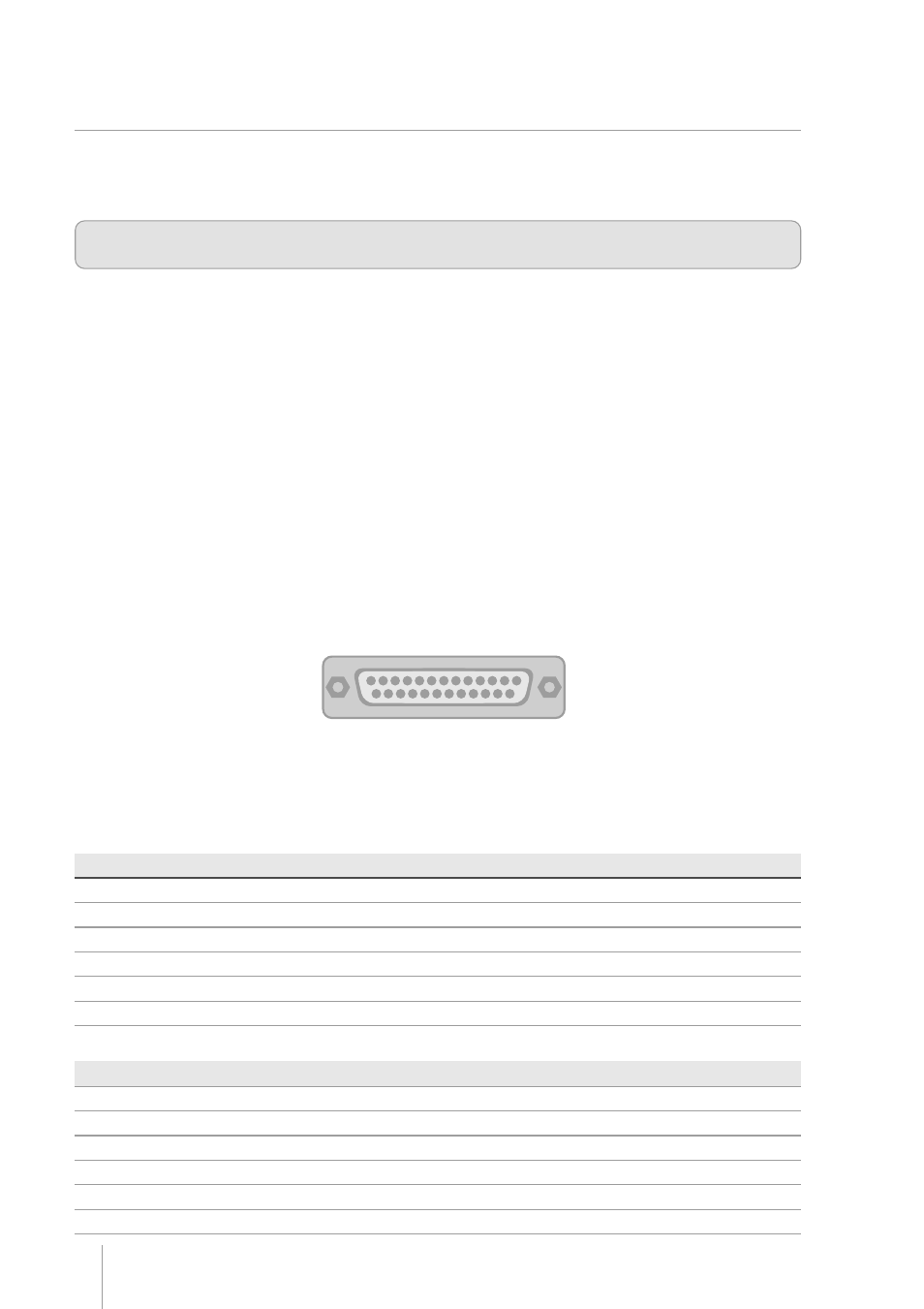
The RS232 serial interface uses a female DB-25 connector. The serial port can operate using the DTR/DSR mode,
with 7 or 8 data bits, with or without parity, even or odd parity, one start bit and one or more stop bits. In the RS232
standard, the logic low level corresponds to a +12V voltage level and a logic high level corresponds to 12V.
DTR / DSR mode
In this mode, the printer’s DTR line controls the flow of data sent from the host’s TX line and received by the printer’s
RX pin. In this case, when the printer’s DTR signal is low (+12V) the printer requests the host to send data. When
the DTR signal is high (-12V) the printer tells the host to stop sending data.
DB-25 Serial connector
Chapter 4
Communication Interfaces
Communication Interfaces
Communication Interfaces
Communication Interfaces
Communication Interfaces
The serial cable needed for the DTR / DSR mode is shown below:
Printer Side (DB-25)
Host Side (DB-9)
2 (TD)
2 (RD)
3 (RD)
3 (TD)
6 (DSR)
4 (DTR)
7 (GND)
5 (GND)
20 (DTR)
6 (DSR)
1-7-8 (jumper)