0 block diagram, 1 atc loops – Broadata Communications 730E-T Series User Manual
Page 5
BCI 730E User’s Manual
Fiber Optic CATV Transmitter
Broadata Technical Support, (800) 214-0222
6
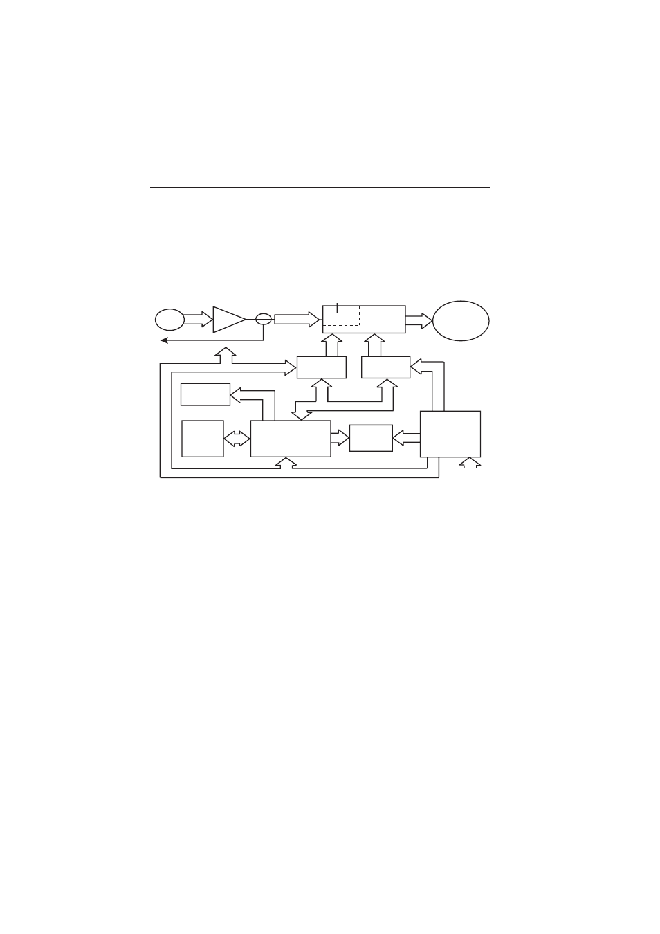
2.0 BLOCK DIAGRAM
The transmitter is based on 4 functional blocks. Optical laser temperature
controlled (ATC), Optical power control electronics (APC), Data
Collection, Controller, Communication Circuit, RF Circuit, and so on.
Figure 2-1
730E-T Block Diagram
2.1 ATC Loops
There is one loop for operating the laser diode at constant optical
output power, as well as at constant temperature by means of
an Auto Temperature Control Loops (ATC). The optical power
and the life-span would be influenced by the temperature of the
heat optical laser. The feasible temperature of the chip is 25
0
C.
The semi conductor laser is sealed in the parts, a temperature
detector resistance is stored in this part.
Predistoration
circuitry
RF
Input
AMP
RF test point
Laser
Output
Cooling/Heating
Controller
Bias
Control
Front Panel
Control
LED
Microcontroller
LCD
Display
Stable
Power
Power