0 panel illustration – Broadata Communications 730E-T Series User Manual
Page 8
BCI 730E User’s Manual
Fiber Optic CATV Transmitter
Broadata Technical Support, [email protected]
9
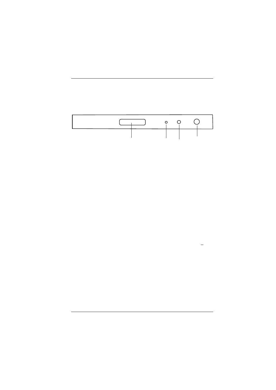
4.0 PANEL ILLUSTRATION
Front Panel
1. LCD
The LCD shows the type of transmitter, output power, laser
temperature, optical laser bias, current cooling/heating and power
voltages, etc.
2. LED Indicator
The laser indicator firstly is lit red when the power is connected. 30
seconds after the transmitter is switched on, the LED is lit green.
3. Status button
Pressing the button will have different status displayed on the LCD.
4. RF Test
RF Test Point is used for monitoring the input RF level. When the
transmitter is in working status, with fiber and coaxial well connected,
the test result will be the same as RF input level, accuracy +2dB.
Please note, RF value is recommended to be tested from RF input
port.
1310nm
AM Laser Transmitter
LASER
SELECT
RF TEST
1
2
3
4