6 network termination – Bronkhorst PROFIBUS-DP slave interface User Manual
Page 11
BRONKHORST
®
2.6
N
ETWORK TERMINATION
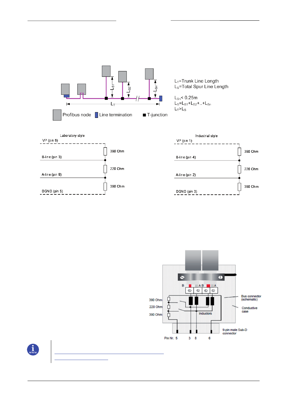
A PROFIBUS DP network segment is based on an RS485 standard and requires two (2) and only two (2), termination
resistor networks, at each of the furthest ends of the PROFIBUS DP cabling. These resistor networks are integrated in
the IP20 connectors and can be enabled by a slide switch on the side of the connector. If connectors without these
integrated resistors are used, a special termination plug containing this resistor must be placed.
Example of a VP = 5V bus termination network.
To allow correct bus termination, each station must connect the signals DGND and VP (5 V) to pins 5 and 6 of the
connector, respectively. The 5 V supply for the terminating resistors (VP) should have a minimum current rating of 10
mA (the current load can increase to 12 mA if a NULL signal is sent through the bus). The current rating should be
increased to app. 90 mA if you need to be able to supply other types of devices on the bus such as bus terminals and
optical fiber cable drivers.
The electrical equipment in a plant is generally connected to a functional ground. It is used to lead away potential
equalization and interference currents and to ensure compliance with EMC regulations and should thus be installed
with regard to the requirements of high frequency currents
.
Due to the capacitive load of the station and the resulting
cable reflections, bus connectors should be provided with
built-in series inductors as shown below.
Due to the built-in series inductors in the bus connectors,
all bus connectors in the network should be attached to the
field bus.
References:
Page 11
PROFIBUS DP interface
9.17.025