2 field bus installation, 1 general, 2 profibus connector – Bronkhorst PROFIBUS-DP slave interface User Manual
Page 8: 2field bus installation, 2 profibus
BRONKHORST
®
2
FIELD BUS INSTALLATION
2.1
G
ENERAL
The following installation guidelines only apply to data transfer using copper cables (RS 485) to EN
50170. Furthermore, operators of PROFIBUS equipment are strongly recommended only to use field bus
devices and components which have been certified by the PROFIBUS User Organization e.V. (PNO).
Certified products have undergone extensive tests carried out by specialists to demonstrate their
compliance to the PROFIBUS standard EN 50170 in combination with PROFIBUS devices from other
manufacturers. PROFIBUS data transfer is based on the RS 485 standard
1
. The relevant features for use
with PROFIBUS-DP are described in EN 50170.
PROFIBUS DP field bus wiring is the cause of many problems if not proper installed.
Please use the instructions below and those mentioned o
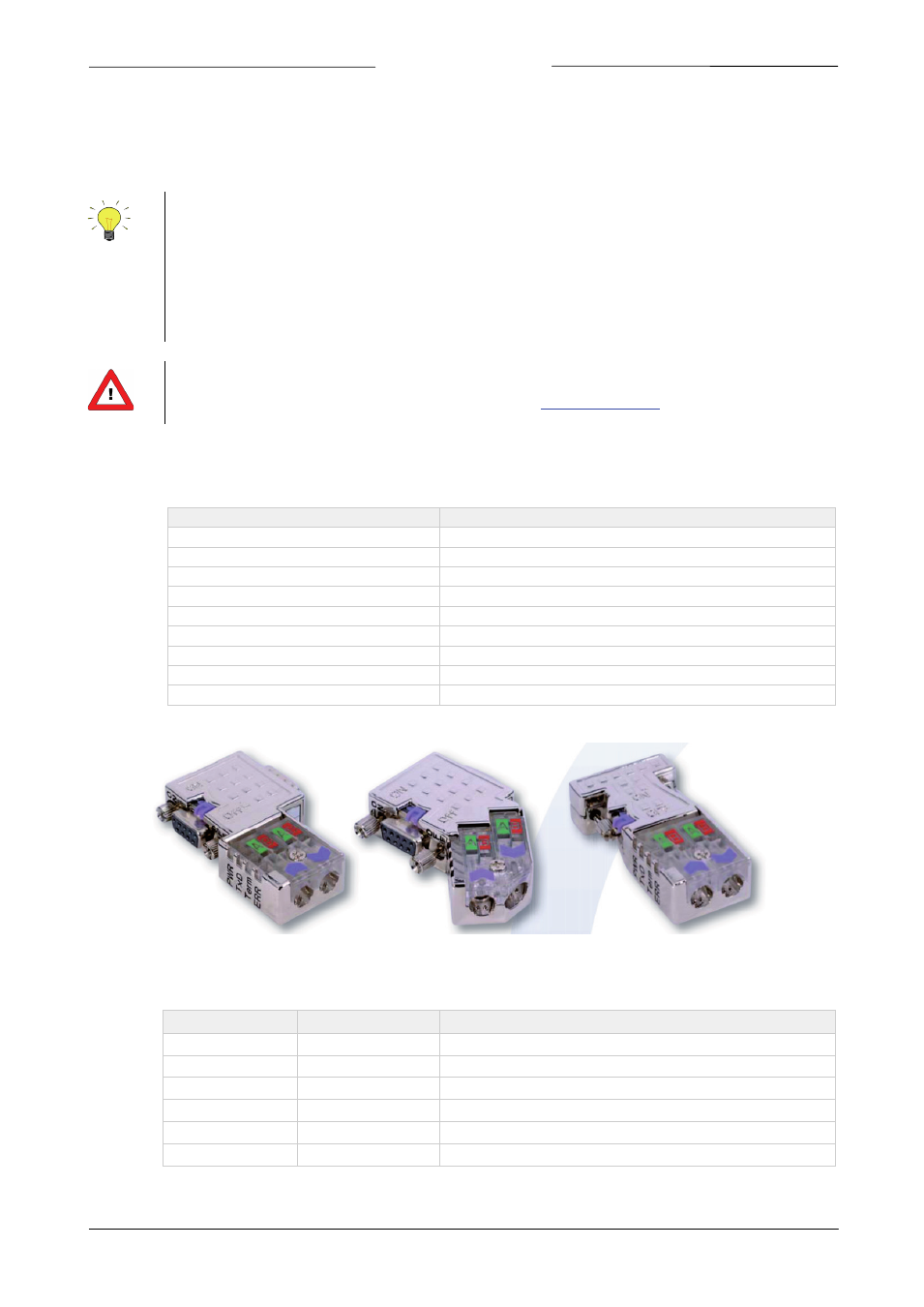
2.2
PROFIBUS
CONNECTOR
The chassis female PROFIBUS DP (sub miniature 9-pin) D-connector has the following pin configuration:
Pin number
Description
1
not connected
2
not connected
3
RxD/TxD-P
-
plus (B – wire)
4
RTS
5
DGnd
6
VP(+5V)
7
not connected
8
RxD/TxD-N
-
minus (A - wire)
9
not connected
The chassis female PROFIBUS M12 B-coded connector (IP65) has the following pin configuration:
Pin number
Signal
Description
1
VP
Power supply plus, (P5V)
2
RxD / TxD-N
Receive / Transmit data –N, A-line
3
DGND
Data ground (reference potential to VP)
4
RxD / TxD-P
Receive / Transmit data –plus, B-line
5
not connected
Thread
Shield
Shield or PE
Page 8
PROFIBUS DP interface
9.17.025