Basic application structure, Standard driver vi structure, 1 basic application structure – Bronkhorst FLOW-BUS LabVIEW Driver User Manual
Page 10: 2 standard driver vi structure
FLOW-BUS LabVIEW™ Driver Manual
9.17.078
Bronkhorst®
10
3.2.1
Basic Application Structure
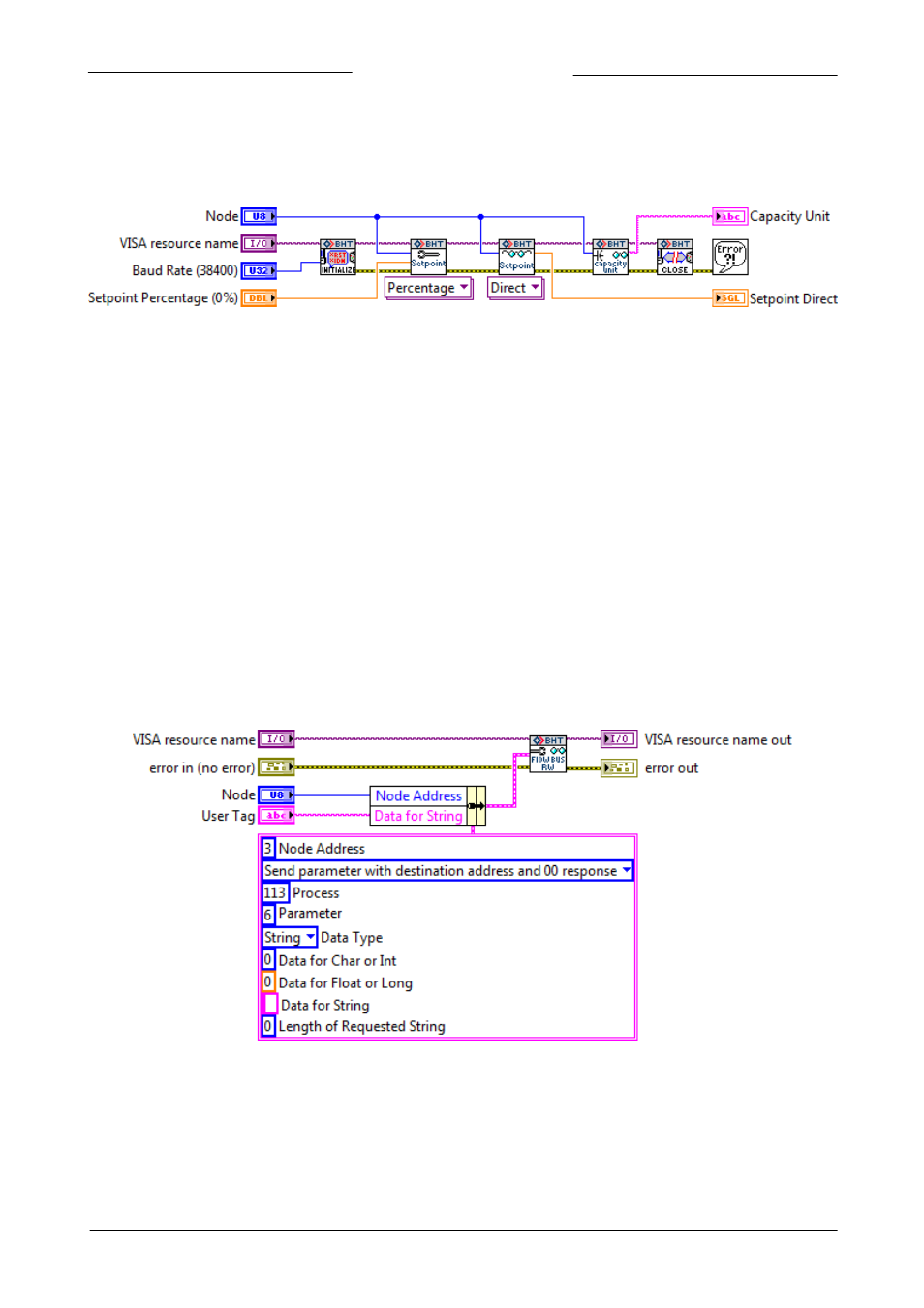
The block diagram below shows an example from the example folder in the driver project. It concerns the Setpoint Configure and
Read VI. This example initializes the connection, writes the setpoint (percentage) and reads back the setpoint (direct) and capacity
unit from the selected instrument. After all values are read and written, the connection is closed and the program stops.
Figure 6: Setpoint Configure and Read VI
This is just an example of a very basic application using only a few of the VIs available. Bigger and more advanced applications can
incorporate loops, case structures and events to create interactive front panels. These more advanced applications can be used to
configure instrument settings and display the data read back from the instrument. An example of such an application is the
Bronkhorst FLOW-BUS Instrument Control Application VI in the Examples folder.
The Initialize- and Close-VI need to be present in every application. Those two VIs are used to open the connection to the COM
port with the correct settings, and to close that connection when the application is finished. Without proper initialization
communication to the instrument is not possible, and not closing the connection can result in errors when using the COM port in
other applications.
LabVIEW™ applications can be made as complex as you need them to be. Just make sure that all VISA and Error connections are
connected, initialized, and closed properly to insure correct operation.
To add functionality to the driver some knowledge of the driver VI structure is needed. This information is available in the next
chapters. Parameter properties can be found in the parameter properties table in document 9.17.027.
3.2.2
Standard Driver VI Structure
The image below shows the block diagram of the Configure Counter Limit VI, which can be found in the Configure » Counter
folder. This VI configures the counter limit/batch in units selected with the Configure Counter Unit VI. The value is a float in IEEE-
754 32-bits single precision notation of which the default setting is 0 ln.
Figure 7: Configure Counter Limit VI
All driver VIs that communicate to an instrument use a FLOW-BUS RW VI. This VI is located in the Private folder that corresponds to
the VIs function. The FLOW-BUS RW VI takes the values from the input cluster and uses these values to create a command string
that complies with the FLOW-BUS protocol. The values needed to read from, or write to, a specific parameter can be found in the
parameter properties table in document 9.17.027. In the cluster in the image above you can see all the settings to configure the
counter limit. These inputs are: