6 ......setup and operation, Setup and operation – BUG-O Systems CB-2 User Manual
Page 6
6
SETUP AND OPERATION:
**All page numbers referred to in this section are from this manual unless otherwise specified.**
POWER SUPPLY: Uses standard 120/50-60/1 VAC or 240/50-60/1 VAC. The part number indicates
voltage. (CBO-2000 and CBO-3000 are 120 VAC and CBO-2002 and CBO-3002 are 240 VAC).
OXY-FUEL CUTTING TORCH: The CB-2, CB-3 Circle Burner is equipped with a Victor 2-Hose Machine
Oxy-Fuel Torch model 204-A w/rack. Refer to the Victor Oxy-Fuel Cutting Torch instruction manual
supplied with this machine for general operation and set-up information. -H Machines are supplied with a
Harris torch.
FIXTURING: All circle burners (excluding CB-2) have to be fixtured in some manner from the top of the
shaft. This may be achieved in one of the following; column & boom, manipulator or a fixture devise.
OXYGEN / FUEL CONNECTIONS: The CB-2, CB-3 Circle Burner is designed to accept standard oxy-
fuel hose fitting connections. These connections are located at the top of the shaft on all models.
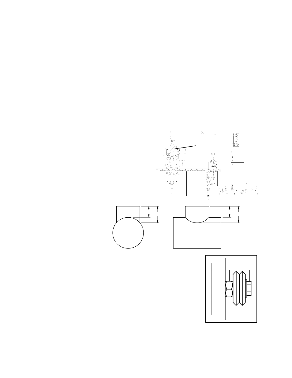
SETTING THE CAM: The cam setting is
equal to the distance “B” subtracted from
the distance “A”.
RISE AND FALL OF THE CAM: All circle burners are
equipped with a rise and fall cam assembly. The cam
assembly must be aligned before any other settings can
be made. To align the cam on the machine, align the
horizontal rack parallel to the pipe
(on the CB-2 align the
horizontal rack parallel to the frame with the torch next
to the frame). Adjust the gun holder so it is perpendicular
to the horizontal rack. Loosen the set screws in the brass
block on the cam, and rotate the cam to the vertical position
as shown.
*For detailed information on burning hillside holes see p.27
MACHINE CONTROLS: Various speed and directional capabilities can be controlled using the CWO-6210
Rotation Control. Please refer to CWO-6210 Rotation Control (page 21) section in this manual.
WHEEL ADJUSTMENT: The CB-2, CB-3 Racking System CWO-1635 (Item #3
page 11 or 13) and the Large Horizontal Racker CWO-1690 (Item #4 page 11 or
13) are equipped with adjustable wheels. Always check these components for
proper wheel adjustment before using the machine. The wheels need adjustment
if you can cock or wiggle the components out of alignment. The wheels should
be snug but not prohibit movement along the path of travel. The wheels with the
hex stand off are adjustable. To adjust the wheels loosen the hex bolt (A) until the
adjustable bushing (B) can be rotated. Correct the wheel alignment by rotating
the adjustable bushing (B). Once adjusted, hold the adjustable bushing (B) while
tightening the hex bolt (A). Recheck alignment.
EXAMPLE:
Let A=3 and B=2
3-2=1
The cam setting is 1.
B
A
Frame
Horizontal Rack
Cam
B
A
B
A