Introduction, Scope of this manual, What’s in the box – Cloud Electronics CDI-S100 User Manual
Page 4: Installation, Configuring the cdi-s100, Installation configuring the cdi-s100
CDI-S100 Installation Guide v1.0
4
Introduction
The CDI-S100 is an optional RS-232C interface
card designed specifically for use with the
Cloud CX462 Audio System Controller. It
allows the CX462 to be controlled by third-
party systems (such as Crestron, AMX, etc.),
using RS-232C serial data.
When installed, the CDI-S100 permits the
following CX462 functions to be controlled
remotely:
•
Music source selection
•
Music level
•
Music muting
•
Muting of individual microphones
•
Master microphone level
•
Master microphone muting
Physically, the CDI-S100 is a small printed
circuit board (PCB), which is retrofitted
internally in the CX462 such that the 9-pin
D-type RS-232C connector is available at the
rear panel.
Scope of this manual
This manual describes the mechanical
installation of the card and the connections
that need to be made to it. It also explains
the various configuration options that the
card offers, and the various jumper and switch
settings that need to be made in the CX462 to
achieve correct operation.
The manual also gives a general overview of
the RS-232C serial control protocol used by
the CDI-S100, and some examples of the most
useful commands. This information should be
adequate for most installations, but please note
that a full description of the RS-232C protocol
is beyond the scope of this manual. The full
protocol can be found at
What’s in the box
•
CDI-S100 PCB
•
Installation Guide (this document)
•
2 qty M3 x 25 mm mounting pillars
Installation
Configuring the CDI-S100
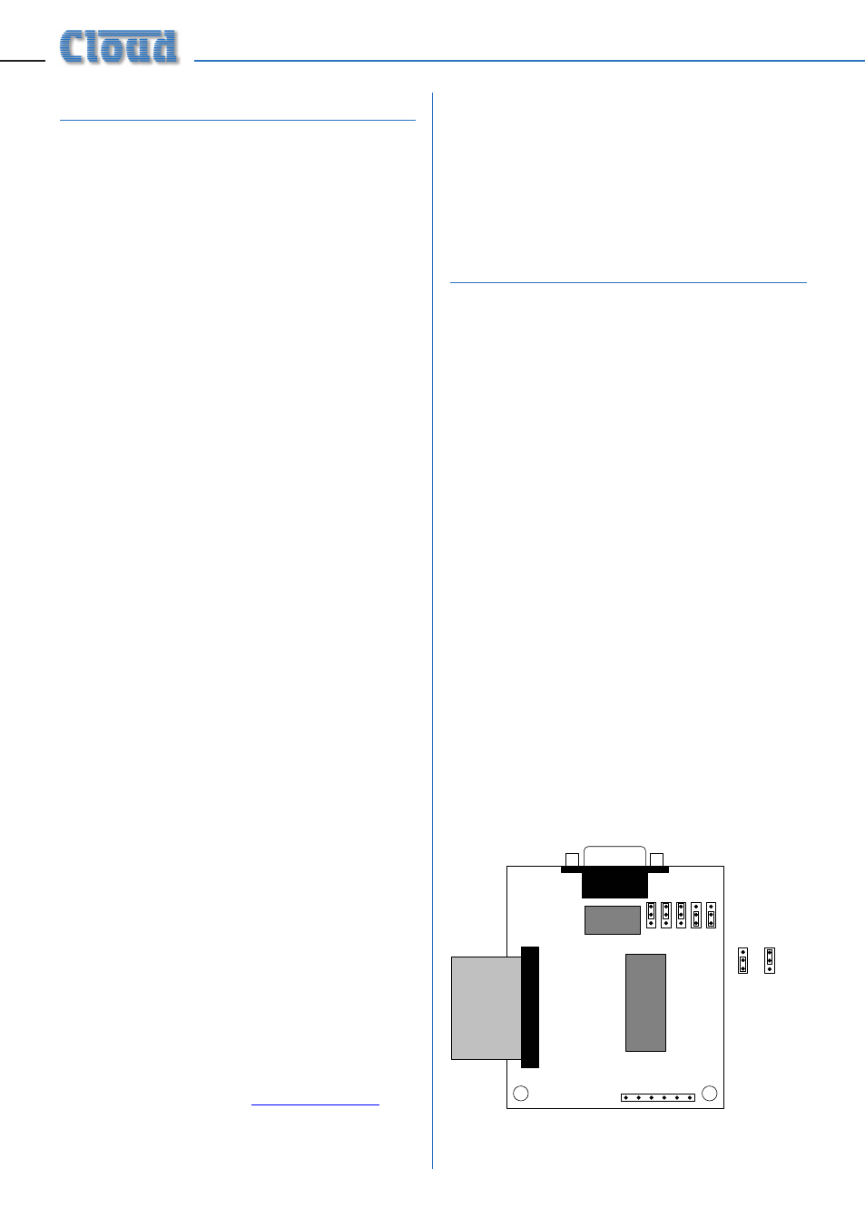
Before installing the CDI-S100 in the CX462,
various jumpers on the PCB need to be set
correctly. (This step should be performed first
because the PCB is installed in the CX462
upside-down, and access to the jumpers is very
difficult once it is in position.)
The jumpers are concerned with setting
the parameters of the serial port (see
“Port parameters” on page 7). The port
parameters should be set to suit the control
system being used. It is quite likely that the
factory default settings will provide correct
operation; nevertheless, it is important to
check that this is so and alter the settings if
necessary.
To move the jumpers, use small pliers to gently
pull the jumper off the header pins and replace
in the correct position. Do not use undue
force, and do not use pliers which are too big.
There are five jumpers, J1 to J5.