Cx462 jumper settings cx462 switch settings, Remote type, Digital – Cloud Electronics CDI-S100 User Manual
Page 6: Local/remote, Remote, I.e., in its ‘in’ position. the front panel
CDI-S100 Installation Guide v1.0
66
4. Screw the threaded ends of the two
25 mm mounting pillars supplied with the
CDI-S100 into the holes vacated by the
screws removed in Step 3.
5. On the CDI-S100 board, remove the two
small threaded bushes on the D-type
connector; retain them. An M3 nut-driver
is the best tool for this. Note that these
bushes also retain the metal connector
shell – be careful to keep it in place
during the next two steps.
UNSCREW THESE
TWO BUSHES
RETAIN METAL SHELL
REAR VIEW OF CDI-S100 PCB
6. Plug the connector on the end of the
ribbon cable into connector CON7 on
the CX462 main PCB. Note it can only be
inserted one way round, with the cable
exiting to the left.
7. With the CDI-S100 PCB upside-down,
insert the D-type connector through the
hole in the rear panel. You will see that the
two holes at the other end of the PCB are
aligned with the mounting pillars fitted in
Step 4. Fix the board to the pillars using
the screws removed in Step 3.
8. Replace the two bushes removed in Step
5 adjacent to the D-type connector by
screwing them through the rear panel.
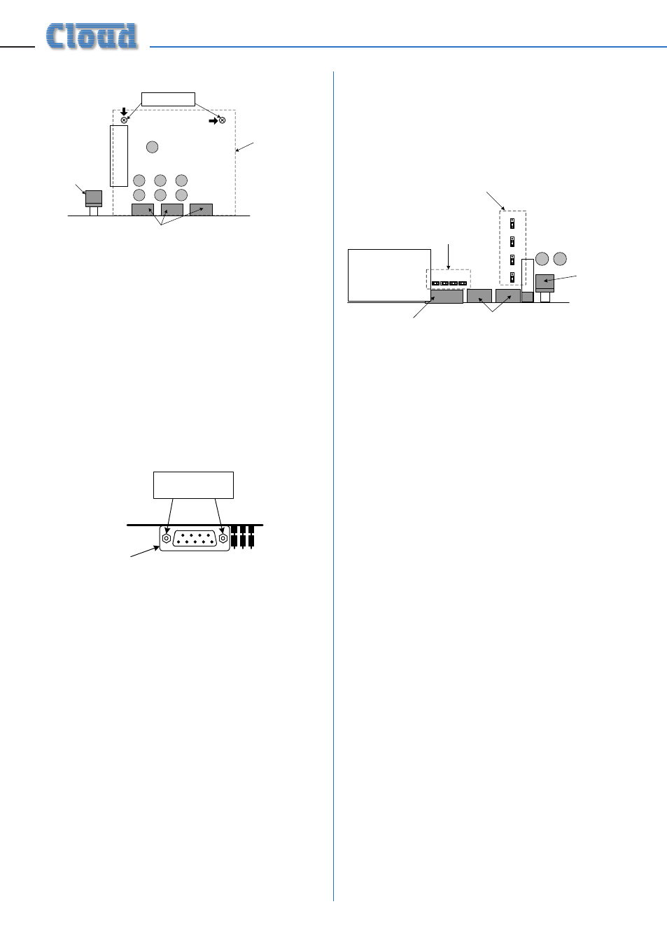
CX462 jumper settings
In order for the CDI-S100 to fully control the
CX462, it is necessary to correctly set some
jumpers on the CX462 main PCB. These are J1
to J4, and J7 to J10.
MIC PREAMP
PCB
MIC ACCESS
CONNECTOR
REMOTE CONTROL
CONNECTORS
REAR EDGE
OF MAIN PCB
LINE 1
GAIN
CONTROL
J1 - J4
MUST BE
IN PLACE
J7 - J10 MUST ALL BE IN
THE ‘SW’ POSITION
J1 J2 J3 J4
LOCATION OF CX-462 JUMPERS
LOCATION OF CX-462 JUMPERS
Jumpers J1 to J4 are all on 2-pin headers, and
can thus be present or absent. They determine
how the CX462’s microphone access control
operates. When a CDI-S100 PCB is installed, all
four jumpers must be present.
Jumpers J7 to J10 determine how music
source selection and music level are controlled
remotely. When an CDI-S100 PCB is installed,
all four jumpers must be in the ‘SW’ position.
To move the jumpers, use small pliers to gently
pull the jumper off the header pins and replace
in the correct position. Do not use undue force,
and do not use pliers which are too big.
CX462 switch settings
After the CDI-S100 card has been fitted, and
J1 – J4 and J7 – J10 set as described above, the
top cover of the CX462 may be replaced, using
the original screws.
The blue rear panel switch
REMOTE TYPE
(adjacent to the REMOTE LINE SOURCE/
LEVEL CONTROL connector) should now be
set to
DIGITAL
– i.e., in its ‘in’ position.
The front panel
LOCAL/REMOTE
button
(adjacent to the mains switch) should be set to
REMOTE
(with the LED on).
The CX462 is now ready for serial remote
control.