System control and alarm relay board (optional), Relays, Table 3-2: scarb relay outputs – Codan Radio MT-4E Paging User Manual
Page 37
MT-4E PAGING SYSTEMS | USER GUIDE
Chapter 3: MT-4E Paging System Components Page 29
SYSTEM CONTROL AND ALARM RELAY BOARD (OPTIONAL)
The System Control and Alarm Relay Board (SCARB) is a module developed to handle alarm outputs
and to add control functionality to MT-4E systems.
Relays
The SCARB contains fi ve standard relays and three optional relays. The standard relays are for
Transmitter Forward Power Alarm, Transmitter VSWR Alarm, Paging Reference Failure Alarm, 100
Watt Power Amplifi er Alarm and AC Power Supply Failure Alarm.
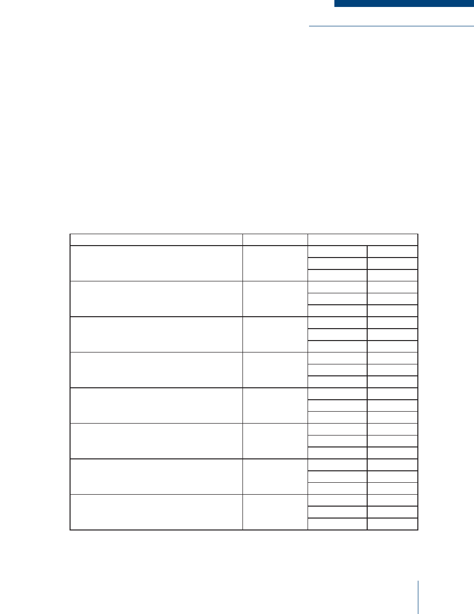
These relays have normally open (N/O), normally closed (N/C) and common (COMM) outputs. Table
3-2 lists the standard confi guration with available alarm lines and their associated relays and connector
pins.
Table 3-2: SCARB Relay Outputs
Alarm Line
Relay
Connectors
Transmitter (A and/or B) Forward Power Alarm
(transmitter power output drops
below half of the set level)
RLY1
J4-11
N/O
J4-12
COMM
J4-13
N/C
Transmitter (A and/or B) VSWR Alarm
(transmitter VSWR is higher than 3:1)
RLY2
J4-14
N/O
J4-15
COMM
J4-16
N/C
Paging Reference Failure Alarm
(external reference fails or drifts to far)
RLY3
J5-10
N/O
J5-11
COMM
J5-12
N/C
100 Watt Power Amplifi er Alarm (Input J5-8)
(power amp output power drops to 80%; or
VSWR exceeds 2.5:1; or high temperature)
RLY4
J2-13
N/O
J2-14
COMM
J2-15
N/C
AC Power Supply Failure Alarm (Input J5-9)
(AC power failure)
RLY5
J6-1
N/O
J6-2
COMM
J6-3
N/C
Spare Alarm 1 (Input J6-4)
(open/ground or variable voltage activation)
RLY6
J6-7
N/O
J6-8
COMM
J6-9
N/C
Spare Alarm 2 (Input J6-5)
(open/ground or variable voltage activation)
RLY7
J6-10
N/O
J6-11
COMM
J6-12
N/C
Spare Alarm 3 (Input J6-6)
(open/ground activation or Low System Voltage
Alarm Option - 10 Vdc or 11 Vdc activation)
RLY8
J6-13
N/O
J6-14
COMM
J6-15
N/C