3 demodulator, 3 demodulator 5.3.1 description, 2 specifications – Comtech EF Data SDM-9000 User Manual
Page 139
SDM-9000 Satellite Modem
Theory of Operation
Rev.4
5–11
5.3 Demodulator
5.3.1 Description
The demodulator PCB fits in the bottom slot of the modem chassis. The demodulator
converts PSK and QAM modulated carriers within the 50 to 180 MHz range to a
demodulated baseband data stream. The demodulator then performs FEC on the data
stream, using the Viterbi decoding algorithm.
The converted modulation types are:
•
QPSK
•
8PSK (optional)
•
16QAM (optional)
Refer to Section 5.6 for a description of the modulation types. Figure 3-3 shows the
demodulator PCB. A block diagram of the demodulator is shown in Figure 5-4, and all
demodulator jumper settings are listed in Table 3-3.
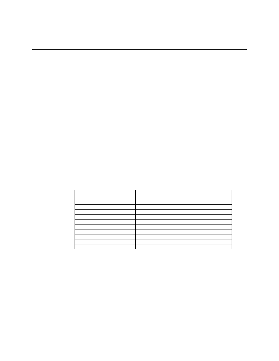
5.3.2 Specifications
Modulation Types
QPSK
8PSK (optional)
16QAM (optional)
Data Rate Range
6.0 to 52.0 Mbit/s (four data rate plug-on module)
Symbol Rate Range
1.7 to 37.6 Ms/s
IF Frequency
50 to 180 MHz, in 2.5 kHz steps
Input Power (Desired Carrier)
-45 to -25 dBm
Input Impedance
75
Ω
(50
Ω
optional)
Input Return Loss
> 18 dBm
Forward Error Correction
Viterbi k=7
Carrier Acquisition Range
±
60 kHz
Filtering Type
Nyquist