4 interface – Comtech EF Data SDM-9000 User Manual
Page 63
SDM-9000 Satellite Modem
Configuration
Rev.4
3–5
3.4 Interface
The interface PCB (AS/3971, AS/4477, or AS/5618) is located in the middle slot of the
modem chassis. The three interface configurations are:
AS/3971
G.703
AS/4477
ECL/MIL-STD-188-144
AS/5618-3
G.703 with 64 kbit/s ESC
Note: The AS/5618-3 G.703 interface assembly supports one 64 kbit/s data channel or
two 32 kbit/s audio channels (per IESS-308, Rev. 8A). The modem can provide
independent transmit (TX) and receive (RX) of audio or digital 64 kbit/s data. This
allows four possible applications:
•
TX and RX: one 64 kbit/s data channel
•
TX and RX: two 32 kbit/s audio channels
•
TX: one 64 kbit/s data channel while RX: two 32 kbit/s audio channels
•
TX: two 32 kbit/s audio channels while RX: one 64 kbit/s data channel
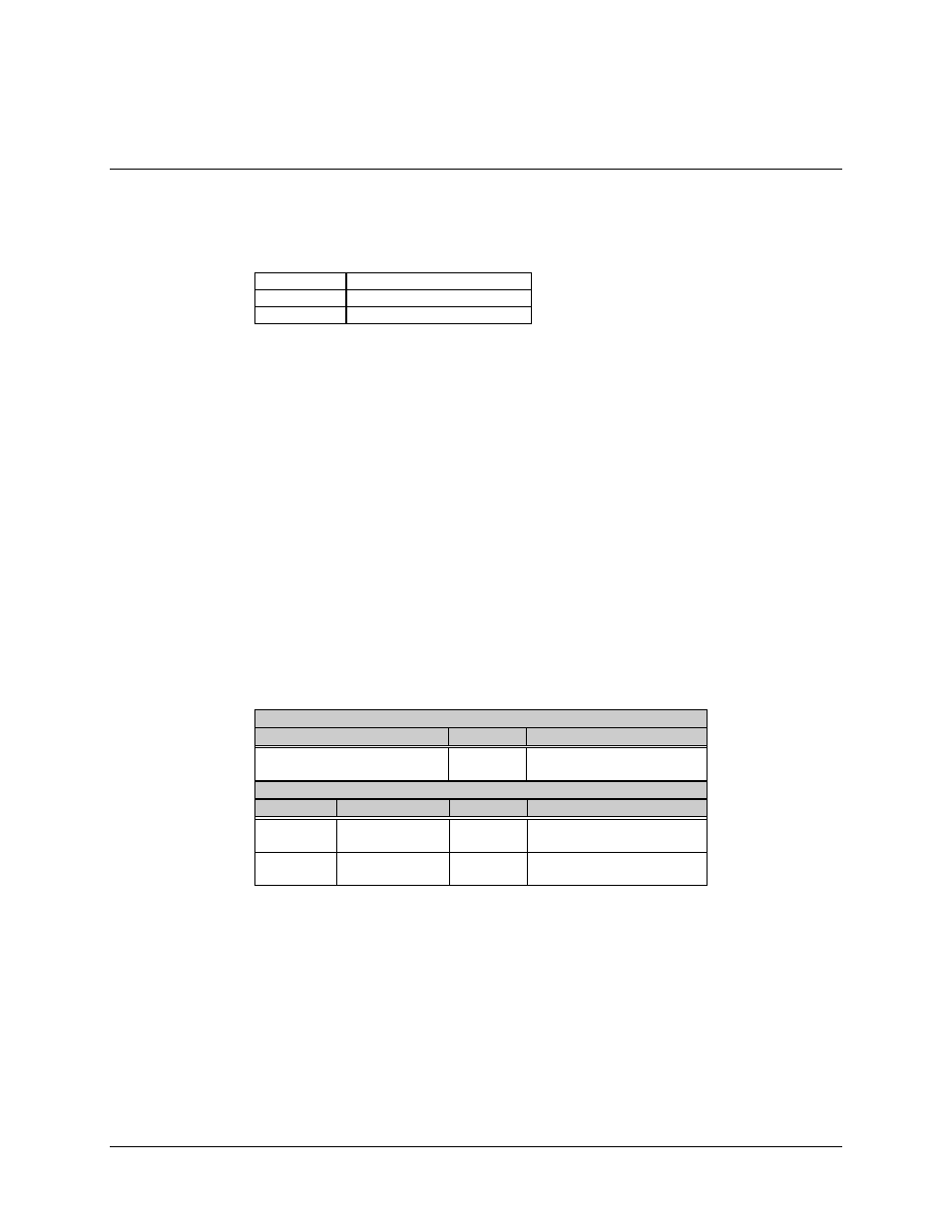
The jumper settings are listed in Table 3-4. Figure 3-4 (AS/3971) and Figure 3-5
(AS/4477) show the interface cards and the locations of jumper JP1.
See Table 3-4 for the appropriate jumper settings for a particular application.
Table 3-4. Interface Configuration Jumper Settings
AS/3971 Interface Only
Jumper
Position
Function
JP1 (EEPROM size select)
1 to 2
2 to 3
27C256 (32K EEPROM)
27C512 (64K EEPROM)
AS/5618-3 G.703 Interface Only
Channel
Jumper
Position
Function
TX
JP7
(Jumper block)
1 to 2
2 to 3
64 kbit/s
Audio
RX
JP6
(Jumper block)
1 to 2
2 to 3
64 kbit/s
Audio
Note: See options, Appendix A for additional timing information.