Comtech EF Data XSAT-7080 User Manual
Page 136
XSAT7080 X-Band Transceiver
Revision 0
50 and 100-Watt Installation
MN/XSAT7080.IOM
B–26
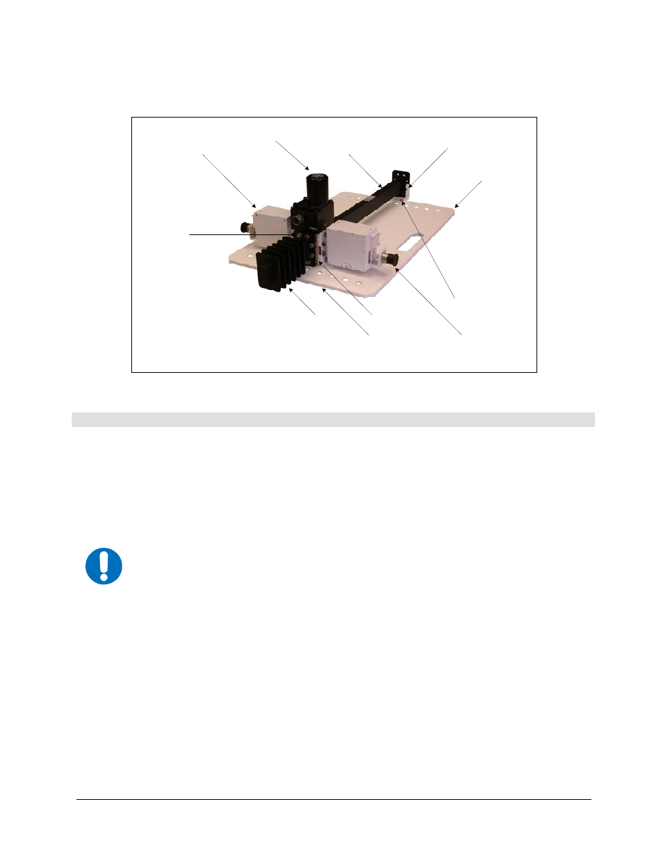
1
2
3
4 (4PLS)
5
6
8
(8 each, 4PLCS)
7 (Underneath)
5
6
9
10
11
Typical LNA
Typical LNA
Figure 2-24. LNA Switch Kit, AS/9751-1 (Shown with Typical LNAs)
Step
Procedures
1
Remove all protective tape from switch and keep it clean.
2
Position Low Noise Amplifiers (LNAs) and gasket (4, Figure B-24) on Port 2 and
Port 4 of switch (11).
3
Secure each LNA with eight bolts (8), lock washers (6) and flat washers (5).
4
Position waveguide termination (3) and gasket (4) on Port 3 and secure with eight
bolts (8), lock washers (6), and flat washers (5).
5
Position filter (10), gasket (4) and use eight bolts (8), lockwashers (6), and flat
washers (5) on remaining port.
IMPORTANT
Ensure that the OUTPUT flange of the filter is against switch (11).
6
Loosely bolt bracket (2) to plate (1) as shown with screws (9), washers (5), and
Lockwashers (6).
7
Secure assembled switch to plate (1) using screws (7) installed through the bottom of
the plate.
8
After Customer-Supplied Input waveguide has been secured to the RF Input, tighten
bracket screws (9). Ensure all hardware is secured.