3 cable connections – Comtech EF Data DT-4500-A Series User Manual
Page 59
DT-4500-A Series Downconverters
Revision 1
Rear Panel Connectors
MN-DT4500A
3–9
PSM Assemblies
CEFD P/N
Impedance
Comments
AS/0101-10
75
Switching, Type ‘N’
AS/0101-11
75
Switching, Type ‘SMA’
AS/0101-24
50
RF Switching, Type ‘N’
AS/0101-30
50
Type ‘SMA’
AS/0101-35
50
Type ‘SMA’ w/isolator
AS/0101-36
75
Type ‘SMA’ w/isolator
EQM Assemblies
CEFD P/N
Impedance
Comments
AS/0101-13
75
EQM for 1:1, C- and Ku-Bands
AS/0101-25
50
1:N IF & RF Switch, Type ‘SMA’
AS/0101-31
75
UT-4514F-A w/isolator
AS/0101-32
50
UT-4514F-A w/isolator
AS/0101-33
75
UT-4518F-A w/isolator
AS/0101-34
50
UT-4518F-A w/isolator
AS/0101-41
50
1:1 Switching
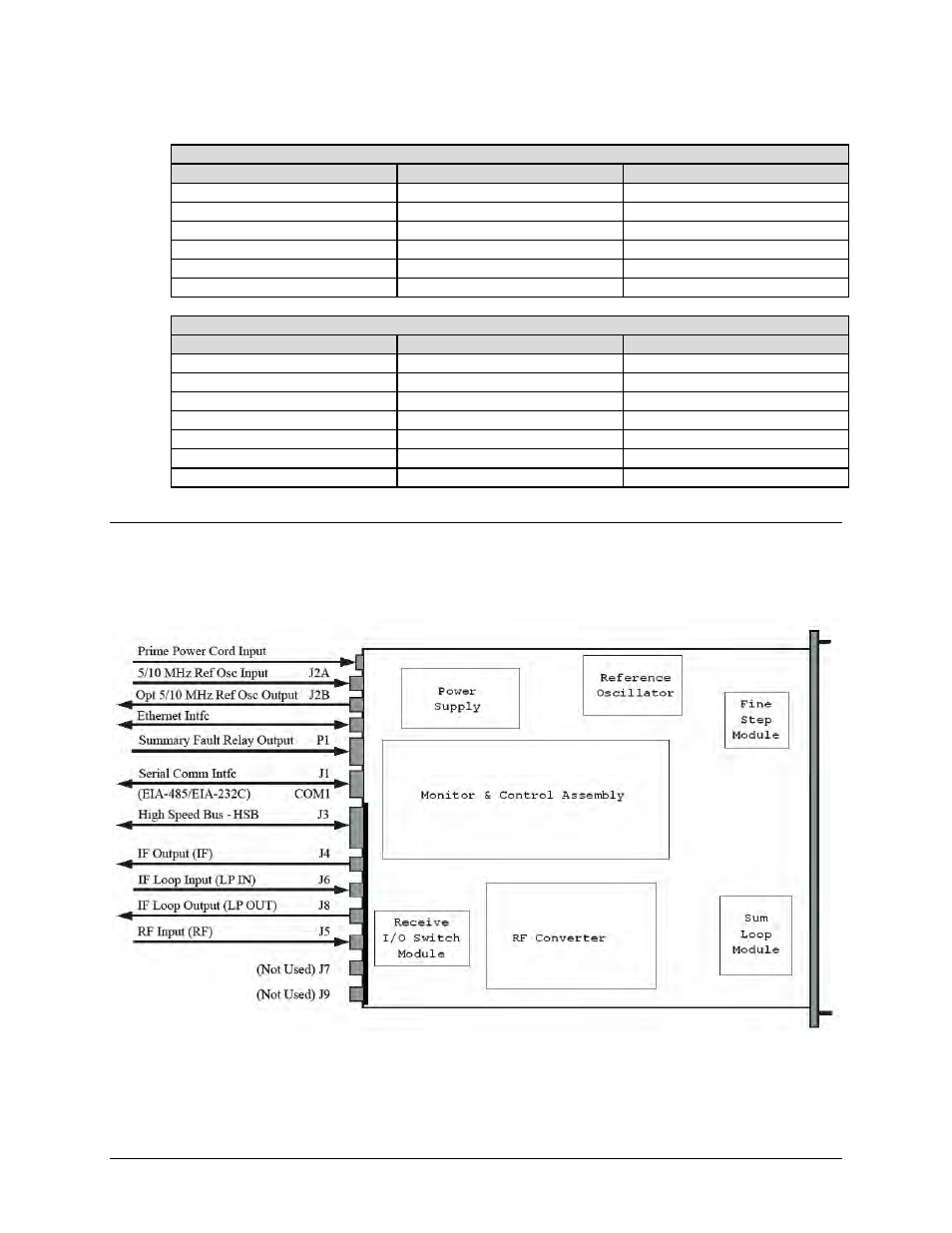
3.3 Cable Connections
Connect the signal cables to the connectors on the rear panel as shown in Figure 3-3. The cable signal
functions are listed in Table 3-1; see Section 3.2 for detailed information about each connector.
Figure 3-3. DT-4500-A Cabling Schematic (DT-4503-A with Receive Switch Module
[RSM-XX] Shown)