Contemporary Control Systems BACnet Cube I/O BMT-DIO4/2 User Manual
Page 2
2
1
6. Mounting
Power down the equipment
Mount the module on standard rail (TH35 per IEC 60715 in
junction boxes and/or on distribution panels).
Installation
Electric installation and device termination shall be done by qua-
lified persons only, by respecting all applicable
specifications and regulations.
Plug in the terminal block for bus connection
4
3
5 mm
5
6
The module can be aligned without interspace. Use the jumper
plug to connect bus and supply voltage when the modules are
mounted in series.
The maximum quantity of modules connected in line is limited
to 15 or to a maximum power consumption of 2 Amps (AC or
DC) per connection to the power supply. For any similar block
of additional modules a separate connection to the power
supply is mandatory.
Connect the cable for bus supply
Mounting in series
7. Network adress and Bit rate setting
Configuration Switches
Hexadecimal Switches x10, x1 define the Network-Address
(00 - F9; e.g. F9h = 15x16+9 = 249d) and Baudrate (FA – FF).
• Turn Switch x10 to E (Device is temporaryly configured as Slave)
• Turn Switch x1 to A – F to select Baudrate
• Turn Switch x10 to F, wait 1 Second
• Red and green LEDs are blinking when Baudrate ist stored in
EEPROM
• Turn Switch x10 to select Network-Address
• Turn Switch x1 to select Network-Address
Factory setting: 9600 Bit/s
Adress switch x10
F
F
F
F
F
F
Adress switch x1
A
B
C
D
E
F
Bitrate (Bit/s)
9600 19200 38400 57600 76800 115200
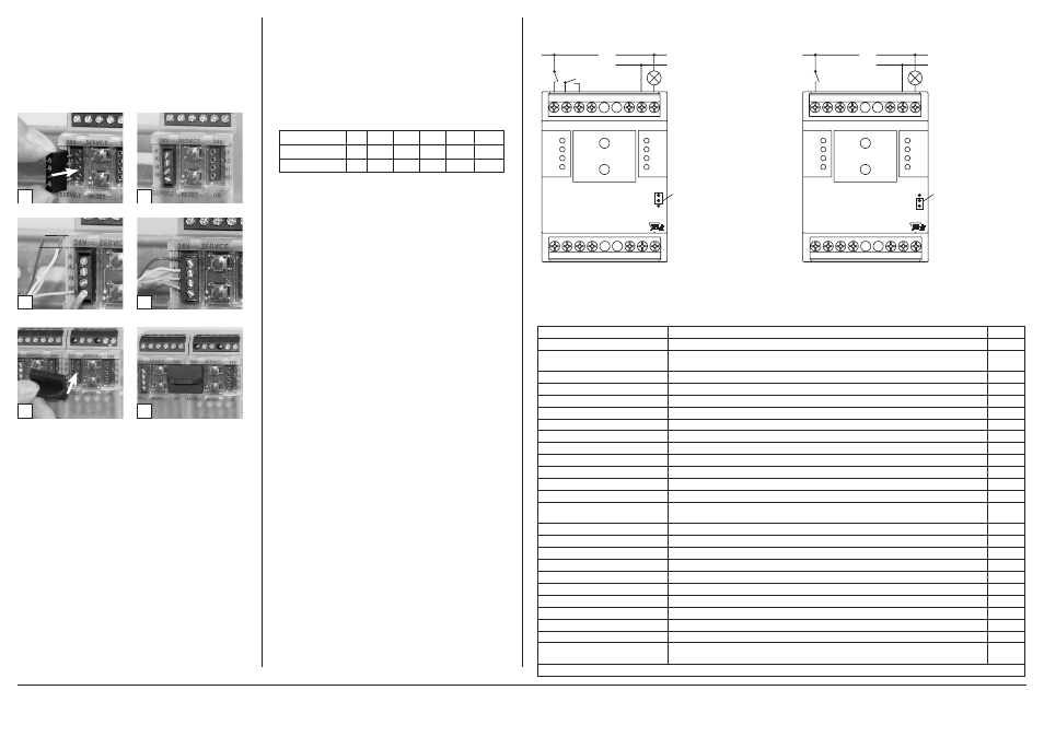
8. Connection examples
Connection examples 1+2
ERROR
24V
1
2
3
4
X10
A-
B+
GND
+24 V
24V
1
2 C1 C1
12 11 14
BUSY
X1
BMT-DIO4/2
BACnet MS/TP
Jumper unter
der Blende
Jumper below
the faceplate
A-
B+
GND
+24 V
4
3 C1 C1
22 21 24
A1 (24 V AC /DC)
N
L
Connection example 3
ERROR
24V
1
2
3
4
X10
A-
B+
GND
+24 V
24V
1
2 C1 C1
12 11 14
BUSY
X1
BMT-DIO4/2
BACnet MS/TP
Jumper unter
der Blende
Jumper below
the faceplate
A-
B+
GND
+24 V
4
3 C1 C1
22 21 24
A2 (GND)
N
L
METZ CONNECT GmbH | Im Tal 2 | 78176 Blumberg | Germany
Phone +49 7702 533-0 | Fax +49 7702 533-433
Mounting instruction see www.metz-connect.com
9. Software Description
Device Object
Property
Remark / Value
RW
Object_Identifier
device, default instance: 421000 + Network-Address
RW-E
Object_Name
max. 63 Bytes,
default “BMT-DIO4/2_” + Network-Address (Hexadecimal)
RW-E
Object_Type
DEVICE (8)
R
System_Status
OPERATIONAL (0)
R
Vendor_Name
“BTR Netcom GmbH”
R
Vendor_Identifier
421
R
Model_Name
“BMT-DIO4/2”
R
Description
max. 127 Bytes, default “”
RW-E
Location
max. 63 Bytes, default “”
RW-E
Firmware_Revision
“1.2”
R
Application_Software_Version
“1.0”
R
Protocol_Version
1
R
Protocol_Revision
12
R
Protocol_Services_Supported
read-property, write-property, subscribe-cov, who-has, who-is, device-communication-
control, reinitialize-device
R
Protocol_Object_Types_Supported
DEVICE, BINARY_OUTPUT, BINARY_INPUT, GROUP, ANALOG_VALUE
R
Object_List [11]
device, binary-output 1…2, binary-input 1…4, group 1…3, analog-value 1
R
Max_APDU_Length_Accepted
480
R
Segmentation_Supported
NO_SEGMENTATION (3)
R
APDU_Timeout
10000
R
Number_Of_APDU_Retries
3
R
Device_Address_Binding
-
R
Database_Revision
0
R
Max_Master
0…127, default 127
RW-E
Max_Info_Frames
1…255, default 1
RW-E
Active_COV_Subscriptions
max. 8 Subscriptions, for binary-input / binary-output,
Confirmed / Unconfirmed, Lifetime = 0…65535 sec.
R
R: Read Property, W: Write Property, -E: Storage in EEPROM / Flash