Contemporary Control Systems Modbus Cube I/O MR-SI4 User Manual
Page 2
2
1
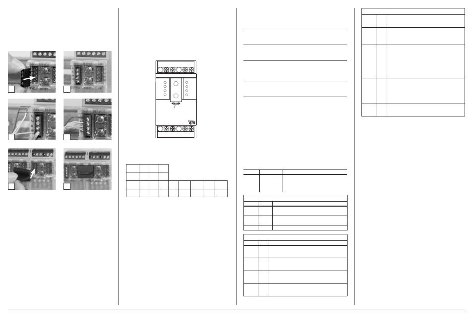
6. Mounting
Power down the equipment.
Mount the module on standard rail (TH35 per IEC 60715 in
junction boxes and/or on distribution panels).
Installation
Electric installation and device termination shall be done by quali-
fied persons only, by respecting all applicable
specifications and regulations.
Plug in the terminal block for bus connection.
4
3
5 mm
6
5
The module can be aligned without interspace. Use the jumper plug
to connect bus and supply voltage when the modules are mounted
in series.
The maximum quantity of modules connected in line is limited
to 15 or to a maximum power consumption of 2 Amps (AC or
DC) per connection to the power supply. For any similar block of
additional modules a separate connection to the power supply
is mandatory.
Connect the cable for bus supply.
Mounting in series.
7. Bit rate and Parity setting
The bit rate and parity can be set in the programming mode when
ajumper is plugged behind the front cover of the module. This
jumper is removed in normal mode. A connection to the bus is not
required during bit rate setting.
The bit rate of the modules can be set in the following way:
1. remove the front cover of the module;
2. plug a jumper to the two middle pins of the 4 pole header
between the red and green LED (Á);
3. set the desired parity and bit rate with the address switches (Â)
in accordance to the chart below.
If the settings differ from the settings specified in the chart the factory
setting applies.
Factory setting: 19200 Bd Even
Switch
x1
1
2
3
4
5
6
7
8
Bitrate
(Bit/s)
1200 2400 4800 9600 19200 38400 57600 115200
Switch
x10
1
2
3
Parity
even odd none
4. switch on the supply voltage of the module; it is now permanent-
ly saving the bit rate in an EEPROM;
5. switch off the supply voltage of the module;
6. remove the jumper from the header and place the front cover.
S02+
S02-
S03+
S03-
S04+
S01+
24V
24V
ERROR
1
A
O
B +
A
-
MR-SI4
B+
A
-
+24V
GND
+24V
GND
BUSY
MODBus RTU
x1
x10
Jumper below
the faceplate
S04-
S01-
METZ CONNECT GmbH | Im Tal 2 | 78176 Blumberg | Germany | Phone +49 7702 533-0 | Fax +49 7702 533-433
Mounting instruction see www.metz-connect.com
8. Software Description
8.1 I/O Commands
“02 (0x02) Read Discrete Inputs”
Request
Valid Input Starting Address
0 .. 3
Valid Quantity of Inputs
1 .. 4
Response
Byte Count
1
Input Status
Bit0 .. Bit3 ( Bit4 .. Bit7 = 0 )
Information
1 = Status Input closed
0 = Status Input open
“04 (0x04) Read Input Registers”
Request
Valid Register Starting Address
20
Valid Quantity of Registers
1
Response
Byte Count
2
(Tabulator kontrollieren )
8.2 Modbus functions
The following functions are used to read or write the registers. The
valid address ranges are indicated in brackets.
Read Input Registers (0-20)
Read Holding Registers (0-43)
Write Single Register (20-43)
Write Single Register (65)
Write Multiple Registers (0-43)
For long data types with a length of several registers, these registers
are listed directly one after the other and the one with the highest
value are indicated first. This data can only be transmitted in com-
plete form.
Discrete Inputs (Read-Only)
Address Name
Description
0 – 3
INPUT
Switching status of the inputs
(switches are connected),
0: Off (switch is open), 1: On
(switch is closed)
Input Register (Read-Only)
Address Name
Description
0 – 11
IZ
Pulse counter
Data type uint48_t (3 registers each)
12 – 19 BZ
Calculated counter reading
Data type uint48_t (2 registers each)
20
INPUT
Bits 0-3 contain Discrete Input 0-3
Holding Register
Address Name Description
0 – 11
IT
Copy of the pulse counter after having pressed
the key
Data type uint48_t (3 registers each) (EEPROM)
12 – 19 AZ
Initial count
Data type uint32_t (2 registers each)
Factory setting 0 (EEPROM)
20 – 23 IE
Pulses per unit
Data type uint16_t (1 register each)
Factory setting 1 (EEPROM)
24 – 27 WI
Current conversion factor
Data type uint16_t (1 register each)
Factory setting 1 (EEPROM)
(continued) Description of the software
28 – 31 WU
Voltage conversion factor
Data type uint16_t (1 register each)
Factory setting 1 (EEPROM)
32 – 35 WP
Operating mode for calculation with conversion factor
Data type uint16_t (1 register each, only bit 0 valid)
Range of values 0…1, see below
Factory setting 0 (EEPROM)
36 – 39 ZS
Format of the counter digit display
Data type uint16_t (1 register each) (EEPROM)
High byte for counter digits,
Range of values 0…9, factory setting 7,
higher values are limited to 9
Low byte for places after the decimal point,
Range of values 0…3, factory setting 1,
higher values are limited to 3
40 – 43 TA
Flag for key activation
Data type uint16_t
(1 register each, flag in bit 0 only)
0: key is locked,
1: key is operational
factory setting 1 (EEPROM)
65
BAUD
Codes for baud rates and parity
Factory setting 19200 baud, Even Parity (EEPROM)
8.3 Operating mode for calculation with conversion
factor
In the WP register, there is a code 0…1 that determines, together
with the conversion factors WI and WU, the way how they are
included in the calculation. WP, WI and WU depend on whether
the converters are switched by the counters, whether the counter
indicates the consumption in a primary or secondary way and whe-
ther the emitted pulses correspond primarily or secondarily to the
consumption.
A difference must be made between the following electricity meter
types:
Type 1:
Directly measuring counter, display: primary,
pulse: primary
Note: Indicates the actual consumption
Species: DIN rail counter with mechanical drum-type counting
mechanism, Ferraris counter
Type of formula:
WP = 0
Factors: WI = WU = 1
IZ – IT
BZ = (---------- + AZ) ∙ WI ∙ WU , BZ = counter reading = consumption
IE
Type 2: Conversion counter, display: primary, pulse: secondary
Note: Indicates the actual consumption
Species: Counter with LCD display
Type of formula:
WP = 1
Factors: WI and WU correspond to the converters
IZ – IT
BZ = (---------- ∙ WI ∙ WU) + AZ , BZ = counter reading = consumption
IE
Type 3: Conversion counter, display: primary, pulse: primary
Note: Indicates the actual consumption
Species: Counter with LCD display, multi-function meters
Type of formula:
WP = 0
Factors: WI = WU = 1
IZ – IT
BZ = (---------- + AZ) ∙ WI ∙ WU , BZ = counter reading = consumption
IE