Contemporary Control Systems Modbus Cube I/O MR-SI4 User Manual
Page 3
METZ CONNECT GmbH | Im Tal 2 | 78176 Blumberg | Germany | Phone +49 7702 533-0 | Fax +49 7702 533-433
Mounting instruction see www.metz-connect.com
(continued) Description of the software
Type 4: Conversion counter, display: secondary, pulse: secondary
Note: Indicates the consumption reduced by the converter factors
Species: DIN rail counter with mechanical
drum-type counting mechanism, Ferraris counter
Type of formula:
WP = 0
Consumption and display of the converter counter are different.
Both can be calculated using a different configuration (WI, WU).
Factors: WI = WU = 1:
The calculated counter reading corresponds to the display
of the converter counter.
Factors: WI and WU correspond to the converters:
The calculated counter reading corresponds to the
consumption.
IZ – IT
BZ = (---------- + AZ) ∙ WI ∙ WU , BZ = counter reading or consumption
IE
8.4. Commissioning
The user reads on site the initial count from the electricity meter and
presses the key on the MR-SI4. After this key press, the pulse counter
of register IZ is copied into register IT.
Afterwards, the user configures the MR-SI4 via the Modbus using a
service program. The following must be entered:
• initial count read from the counter
• pulses per unit,
e.g. indication on the electricity meter 2000 pulses per kWh
• formula type for calculation with converter factors
• factor for current conversion,
e.g. indication on the converter 200/5A → factor = 40
• factor for voltage conversion,
e.g. indication on the converter 20000/100V → factor = 200
• number of digits and places after the decimal point
• deactivate the key to protect the IT register
8.5.Details for calculation
The calculated counter reading should behave exactly in the same
way as the electricity meter. This requires that there should be no
overflows and rounding off errors for the intermediate results.
Therefore, particularly large data types are used for counting and
calculation.
Every 60 milliseconds, a pulse can be emitted by the electricity meter.
This results in up to 1,440,000 pulses per day or about 526,000,000
pulses per year.
If the pulse counter was realized with 4 bytes, it could be count to
4,294,967,295. At highest pulse frequency, this would be enough for
approx. 8.2 years.
Therefore it is realized with 6 bytes and cannot overflow.
The number of places after the decimal point is considered as an ad-
ditional multiplier with a power of ten during the calculation.
Furthermore, it determines the place of the decimal point in the
display of BZ and AZ.
As for the electricity counter which only has a specified number of
decimal places, the number of places is limited with the last step in
the calculation. This is why the calculated counter reading of the MR-
SI4 overflows to 0 as often as the counter reading of the electricity
meter.
Calculated counter reading, if WP is 0.
BZ = ( (uint96_t) (IZ - IT)*WU*WI*Power of ten [places after decimal
point] / IE +
(uint96_t) AZ * WU * WI )
% power of ten [digits]
Calculated counter reading, if WP is 1.
BZ = ( (uint96_t) (IZ - IT)*WU*WI*Power of ten [places after decimal
point] / IE +
(uint96_t) AZ )
% power of ten [digits]
(continued) Description of the software
8.6 Bit rate setting with Modbus command
Parity and bit rate have the same value as when setting them by
address switch.
If Parity or Bit has the value 0, no setting or storage is carried out.
The register content is stored in the EEPROM.
“06 (0x06) Write Single Register”
Request
Valid Register Address
0x41 ( 65 )
Valid Register Value 2 Bytes
Bit 15-8: Magic-Number 0x53 = 83 as protection against
accidental
writing.
The command will be further analysed only with this number.
Response
Echo of Request
Example for a frame:
Slave address
0x12 Setting of rotary switch (18)
Function
0x06 Write Single Register
Register address Hi
0x00
Register address Lo
0x41 Bit rate and parity (65)
Register contents Hi
0x53 Magic-Number
Register contents Lo
0x15 Parity Even, 19200 Baud
All devices can be switched simultaneously with a Broadcast com-
mand (Slave address 0x00) However, it is advised not to do so as this
can cause problems:
- Devices from other manufacturers may have under this
address a register for a different purpose that will then
be operated in the wrong way.
- There is no feedback from the individual devices.
Consequently the control cannot immediately recognize
if the command was correctly received.
It is safer to address and switch each device individually.
The device will then answer with the old settings of parity and bit
rate. Switching will take place only afterwards. However, the answer
can get lost if the bus is disturbed.
When all devices are switched; it is advised to check communication.
Any function of the device providing a feedback is suitable. If a single
function is to be used being independent from the process periphery
then the function „Diagnostic“ sub-function „Return Query Data“ is
suitable, it returns the transferred data.
If bit rate and parity setting of a device are unknown it is possible to
address the device successively with all combinations of bit rate and
parity until the device answers. Try the most likely combinations first.
Try the lower bit rates last as they take longer.
(continued) Description of the software
8.7 General Commands
“08 (0x08) Diagnostics”
Subfunction “0 ( 0x0000) Return Query Data”
Data Field Any
Response: Echo of Request
Subfunction “1 (0x0001) Restart Communication Option”
Data Field 0x0000 oder 0xFF00
Response: Echo of Request
Action: Clears all Error Counters, Restarts node
Subfunction “4 (0x0004) Force Listen Only Mode”
Data Field 0x0000
No Response
Action: No response until Node Reset or Function Code 08
Subcode 01
Subfunction “10 ( 0x000A) Clear Counters”
Data Field 0x0000
Response: Echo of Request
Action: Clears all Error Counters
Subfunction “11 ( 0x000B) Return Bus Message Count”
Data Field 0x0000
Response: Quantity of messages that the remote device has
detected on the communications system since its last restart,
clear counters operation, or power-up.
Subfunction “12 ( 0x000C) Return Bus Communication Error Count”
Data Field 0x0000
Response: Quantity of errors encountered by the remote
device since its last restart, clear counters operation,
or power-up. (CRC, Length <3, Parity, Framing)
Subfunction “13 ( 0x000D) Return Bus Exception Error Count”
Data Field 0x0000
Response: Quantity of MODBUS exception responses returned
by the remote device since its last restart, clear counters
operation, or power-up.
Subfunction “14 (0x000E) Return Slave Message Count”
Data Field 0x0000
Response: quantity of messages addressed to the remote
device, or broadcast, that the remote device has processed
since its last restart, clear counters operation, or power-up.
Subfunction “15 (0x000F) Return Slave No Response Count”
Data Field 0x0000
Response: Quantity of messages addressed to the remote
device for which it has returned no response (neither a normal
response nor an exception response), since its last restart, clear
counters operation, or power-up.
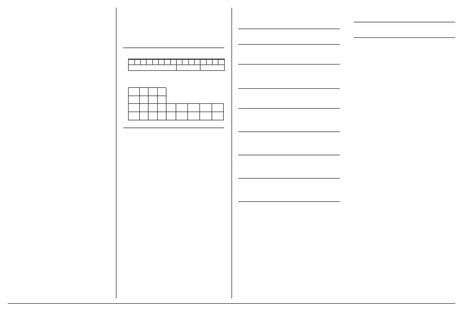
15 14 13 12 11 10 9
8
7
6
5
4
3
2
1
0
0x53
Parität
Bitrate
Bit 3-0
1
2
3
4
5
6
7
8
Bitrate 1200 2400 4800 9600 19200 38400 57600 115200
Bit 7-4
1
2
3
Parität even odd none
(continued) Description of the software
“43 /14 (0x2B / 0x0E) Read Device Identification”
Request
Read Device ID code:
0x01
Object ID
0x00
Response
Device ID code
0x01
Conformity level
0x01
More follows
0x00
Next object ID
0x00
Number of objects
0x03
Object ID
0x00
Object Length
0x03
Object Value
“BTR”
Object ID
0x01
Object Length
0x06
Object Value
“MR-SI4”
Object ID
0x02
Object Length
0x04
Object Value
“V2.0”