Instructions for replacing parts, Replacing a digit panel, Replacing a digit segment – Daktronics DF-2100 User Manual
Page 28: Figure 15: digit assembly, Figure 16: digit segments, 2 instructions for replacing parts
5.2 Instructions for Replacing Parts
Replacing a Digit Panel
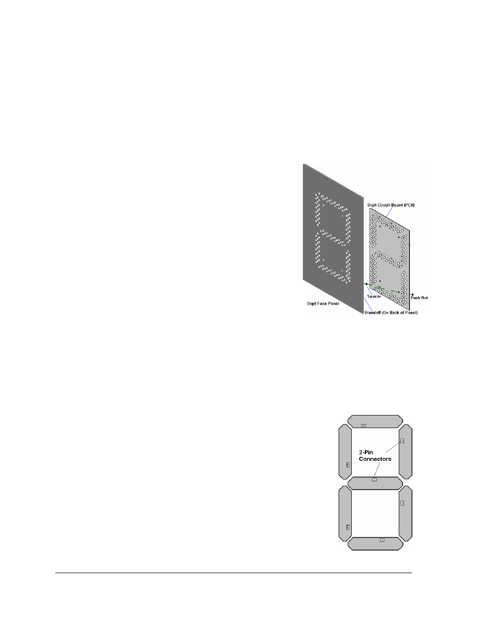
The digit circuit board is the platform for the LEDs and is mounted to the back of the digit
panel. Refer to Figure 14. If some LEDs are not working, do not attempt to remove an
individual LED. Replace the entire digit panel.
To remove a display digit panel, follow these steps:
1.
Open the digit panel as described in Section 4.1.
2.
Disconnect the power/signal connector from the
back of the digit. Release the connector by
squeezing together the locking tabs as the plug is
pulled free.
Figure 14: Digit Assembly
3.
The digits are secured to the inside of the panel
with fixed machine screws, spacers, and push nuts.
Remove the nuts and lift the digit off the standoff
screws. The push nuts can be removed in several
ways, but Daktronics recommends using a 9/32"
nut driver.
4.
Move the new digit into place and install the
pushnuts.
5.
Reconnect the power/signal connector plug. Note:
This is a keyed connector and will attach in one way
only. Do not attempt to force the connection!
6.
Replace the back panel of the display, latching it
securely.
Replacing a Digit Segment
Large digits are constructed in segments, as shown in Figure 15. In this case, it may be
possible to replace only the defective segment. As with smaller digits, the segment circuit
boards are mounted to the back of the digit panel. Do not attempt to remove individual
LEDs. Replace a malfunctioning colon, decimal, or indicator assembly in the same manner.
To remove a digit segment, follow these steps:
Figure 15: Digit Segments
1. Open the digit panel as described in Section 4.1.
2. Disconnect the 2-pin power/signal connector from the back
of the individual segment. Release the connector by
squeezing together the locking tabs as the connector is pulled
free.
3. The individual segments are secured to the inside of the
panel with fixed machine screws, spacers, and push nuts.
Remove the nuts and lift the segment off the standoff screws.
4. Position a new segment over the screws and tighten the nuts.
5. Reconnect the power/signal connector. Note: This is a keyed
connector it will attach in one way only. Do not attempt to
force the connection!
6. Close and secure the digit panel and test the display.
20
DM-100 Controller