2 power wiring, 5 grounding, 1 new power installation – Daktronics CH-1436H User Manual
Page 9: 2 power wiring -3, Grounding -3 2.5.1 new power installation -3
At the display, open the bottom hinged panel covering the entrance enclosure as
shown on Drawing A-63922. Remove the cover from the entrance enclosure. Refer
to Drawing A-63923 for an illustration of the components inside the entrance
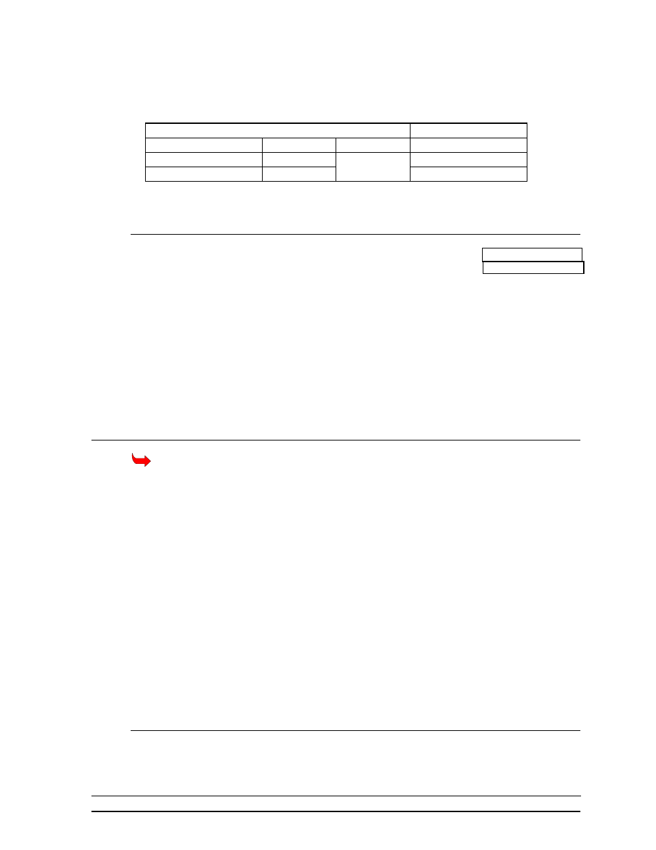
enclosure. Connect the signal wires to TB31 as indicated in the table below.
Control End
Display End
J-box Terminal No.
Wire Color
Output No.
TB31 Terminal No.
14 Red/Wht
1*
1
(+)
15 Grn/Wht
2
(-)
*Auxiliary display(s) require(s) a different output no.(s). Consult your CHTS-300 console
manual.
2.4.2 Power Wiring
Reference Drawings: Connector Plate, CH-1436H ............. Drawing A-63501
Power&Signal Entrance,CH-1436 .... Drawing A-63923
The CH-1436H display requires a 120/240 VAC, 40 amp circuit per line. When
equipped with 30W, 30R20 reflector lamps, the maximum current draw is 54 amps.
Route power wires into the display and connect to TB41 in the entrance enclosure as
shown in Drawing A-63923.
Connect the ground wire to E41 and to a ground rod near the display according to
local codes and Section 2.5.
2.5 Grounding
Displays MUST be grounded according to the provisions outlined in Article 250 of the
National Electrical Code.
The display must be connected to earth-ground. Proper grounding is necessary for reliable
equipment operation. It also protects the equipment from damaging electrical disturbances
and lightning. The display must be grounded as follows or the warranty will be void.
The support structure of the display cannot be used as grounding. The support is generally
embedded in concrete, and if in earth, the steel is either primed or it corrodes, making it a poor
ground. Use one ground rod at each display support column.
The National Electrical Code requires the use of a lockable power disconnect near the display.
Provide a lockable disconnect switch (knife switch) at the display location so that all power
lines can b completely disconnected. Use a 3-conductor disconnect so that both hot lines and
the neutral can all be disconnected.
There are two considerations for power installation: New Power Installation and Existing
Power Installation. These two power installations differ slightly, as described in the following
sections.
2.5.1 New Power Installation
Installation
2-3