Section 3: setup & operation, 1 power & signal connections, 2 setup – Daktronics Sportsound Rack SSR-300 Operation Manual User Manual
Page 17: 3 powering on, Section 3, Setup & operation, Power & signal connections, Setup, Powering on
Setup & Operation
11
Section 3:
Setup & Operation
3.1 Power & Signal Connections
All connections are made upon installation. Some equipment may be connected and
disconnected each time it is used. Drawing C-1102369 in Appendix A shows a general
overview of how standard and optional equipment connects to the rack. Note that every
project is unique, so be sure to follow any site-specific riser drawings and documentation for
the facility to determine the exact layout of system components.
3.2 Setup
The announcer’s interface equipment is typically kept in the bottom storage drawers along
with other accessories. Follow the steps below to properly reconnect it to the rack.
1. Connect one end of the XLR gooseneck to the wired microphone and the other end
into the jack on top of the announcer’s interface. Also plug the wallpack transformer
into a standard power outlet.
Note: The headset microphone may be connected to the announcer’s interface via the
XLR jack and the HEADPHONES jack (on rear).
2.
Connect
the 15' (4.6 m) XLR cable (part # W-2074) from MIC 1 & AUX 1 on the
announcer’s interface to Mic 1 & Aux 1 on the announcer’s plate.
For the 27 RU rack only, there will be a 25' (7.6 m) or 50' (15.2 m) cable harness factory wired
to the rack. Route this cable to the desired mixer location and connect each plug to the
appropriate jack on the mixer according to the wire labels. Plug the mixer into a standard
power outlet.
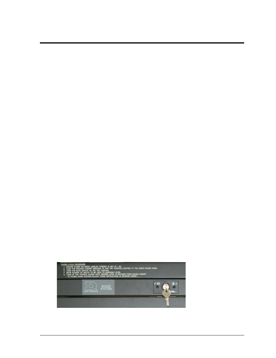
3.3 Powering ON
Unlock the door of the rack, and turn the SOUND SYSTEM key switch (
) to the
ON (vertical) position.
Note: Keep both sets of keys in a safe location to prevent tampering/theft of rack equipment!
Figure 16: Power Key Switch