Chapter 3 - hardware installation, Board layout, Chapter 3 chapter 3 - hardware installation – DFI KS200 Manual User Manual
Page 13
www.dfi .com
Chapter 3 Hardware Installation
13
Chapter 3
Chapter 3 - Hardware Installation
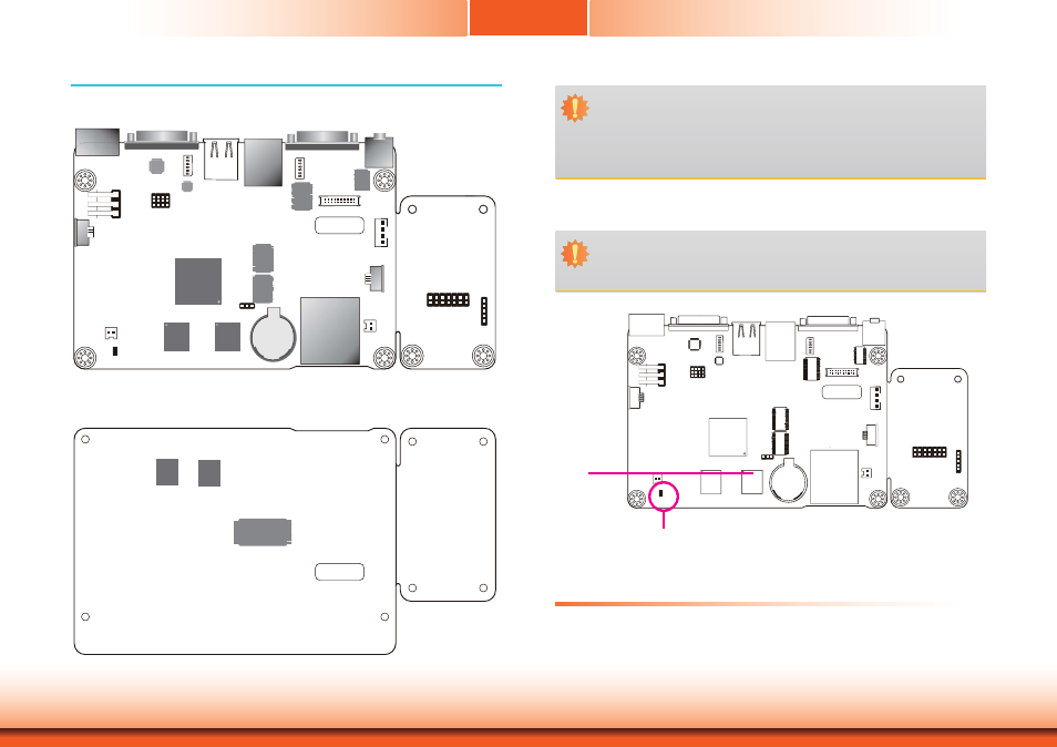
Board Layout
Bottom View
NAND Flash
DDR2
DDR2
128M
128M
COM 1
COM 2
Line-out
3
1
10
12
COM2 RS232/422/485 HW/SW Select(JP7)
SD/MMC
Reset
1
Amplifier 2W
Connector
1
2
19
20
LVDS LCD Panel
LED Connector (external)
USB 1-2
1
ON
234
5
6
Standby Power LED
LAN 1
1
ON
234
5
6
SW3
Touch
Connector
(default)
LVDS83B
1
14
DIO
1
5
Touch
Connector (option)
DC-in
SW4
Power SW
Battery
1
Clear CMOS(JP1)
1
1
1
AM3517AZCN
DDR2
DDR2
128M
Android Hot Key Connector
128M
USB 2514BI
AIC23B
SP338EER1
AVC
16T245
AVC
16T245
Top View
System Memory
DDR2
Important:
Electrostatic discharge (ESD) can damage your board, processor, disk drives, add-in
boards, and other components. Perform installation procedures at an ESD workstation
only. If such a station is not available, you can provide some ESD protection by wear-
ing an antistatic wrist strap and attaching it to a metal part of the system chassis. If
a wrist strap is unavailable, establish and maintain contact with the system chassis
throughout any procedures requiring ESD protection.
Important:
When the Standby Power LED lit red, it indicates that there is power on the system
board. Power-off the PC then unplug the power cord prior to installing any devices.
Failure to do so will cause severe damage to the motherboard and components.
• 512MB
DDR2
onboard
•
Supports 512MB NAND Flash
•
TI TSC2004 touch screen controller
Standby Power LED
Features