Com express connectors signal description – DFI CD905-B2800 User Manual
Page 17
www.dfi .com
Chapter 3 Hardware Installation
17
Chapter 3
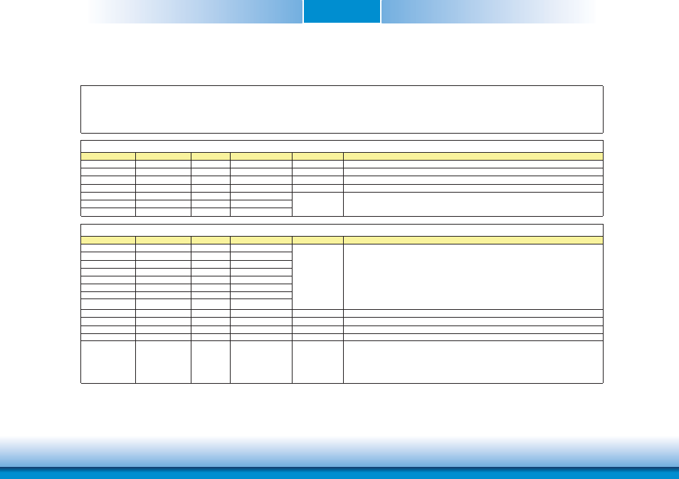
COM Express Connectors Signal Description
Signal
Pin#
Pin Type
Pwr Rail /Tolerance
PU/PD
Description
AC/HAD_RST#
A30
O CMOS
3.3V Suspend/3.3V
Reset output to CODEC, active low.
AC/HDA_SYNC
A29
O CMOS
3.3V/3.3V
Sample-synchronization signal to the CODEC(s).
AC/HDA_BITCLK
A32
I/O CMOS
3.3V/3.3V
Serial data clock generated by the external CODEC(s).
AC/HDA_SDOUT
A33
O CMOS
3.3V/3.3V
Serial TDM data output to the CODEC.
AC/HDA_SDIN2
B28
I/O CMOS
3.3V Suspend/3.3V
AC/HDA_SDIN1
B29
I/O CMOS
3.3V Suspend/3.3V
AC/HDA_SDIN0
B30
I/O CMOS
3.3V Suspend/3.3V
Signal
Pin#
Pin Type
Pwr Rail /Tolerance
PU/PD
Description
GBE0_MDI0+
A13
I/O Analog
3.3V max Suspend
GBE0_MDI0-
A12
I/O Analog
3.3V max Suspend
GBE0_MDI1+
A10
I/O Analog
3.3V max Suspend
GBE0_MDI1-
A9
I/O Analog
3.3V max Suspend
GBE0_MDI2+
A7
I/O Analog
3.3V max Suspend
GBE0_MDI2-
A6
I/O Analog
3.3V max Suspend
GBE0_MDI3+
A3
I/O Analog
3.3V max Suspend
GBE0_MDI3-
A2
I/O Analog
3.3V max Suspend
GBE0_ACT#
B2
OD CMOS
3.3V Suspend/3.3V
Gigabit Ethernet Controller 0 activity indicator, active low.
GBE0_LINK#
A8
OD CMOS
3.3V Suspend/3.3V
Gigabit Ethernet Controller 0 link indicator, active low.
GBE0_LINK100#
A4
OD CMOS
3.3V Suspend/3.3V
Gigabit Ethernet Controller 0 100 Mbit / sec link indicator, active low.
GBE0_LINK1000# A5
OD CMOS
3.3V Suspend/3.3V
Gigabit Ethernet Controller 0 1000 Mbit / sec link indicator, active low.
GBE0_CTREF
A14
REF
GND min 3.3V max
1V9
Reference voltage for Carrier Board Ethernet channel 0 magnetics center
tap. The reference voltage is determined by the requirements of the
Module PHY and may be as low as 0V and as high as 3.3V.
The reference voltage output shall be current limited on the Module. In
the case in which the reference
Pin Types
I Input to the Module
O Output from the Module
I/O Bi-directional input / output signal
OD Open drain output
AC97/HDA Signals Descriptions
Serial TDM data inputs from up to 3 CODECs.
Gigabit Ethernet Signals Descriptions
Gigabit Ethernet Controller 0: Media Dependent Interface Differential
Pairs 0,1,2,3. The MDI can operate in 1000, 100 and 10 Mbit / sec
modes. Some pairs are unused in some modes, per the following:
1000BASE-T 100BASE-TX 10BASE-T
MDI[0]+/- B1_DA+/- TX+/- TX+/-
MDI[1]+/- B1_DB+/- RX+/- RX+/-
MDI[2]+/- B1_DC+/-
MDI[3]+/- B1_DD+/-