Mechanical diagram, Chapter 3 mechanical diagram – DFI CM901-B User Manual
Page 11
www.dfi.com
Chapter 3 Hardware Installation
11
Chapter 3
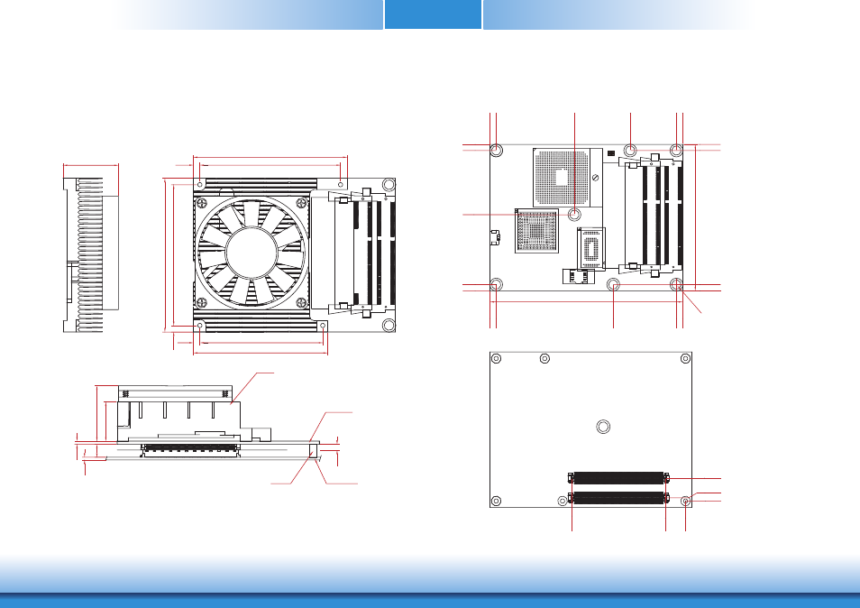
Mechanical Diagram
CM901-B Module with Heat Sink
Side View of the Module with Heat Sink and Carrier Board
CM901-B Module
Ø2.70(*7 pcs)
Bottom View
Top View
Heat sink with fan
Module PCB
Carrier Board
Standoff
0.00
0.00
2.00
14.00
12.50
70.20
0.00
0.00
76.00
117
.00
0.00
4.00
121.00
4.00
4.00
87.00
91.00
4.00 0.00
87
.00
87.00
121.00
117
.00
91.00
125.00
95.00
50.80
45.34
2.00
Module PCB
The height
of the highest parts
3.50
1.60
24
.20
34
.20
8.00
4.00
87.00
95.00
4.00
87
.00
4.00
76.00
95.00
83.00
34.20