Chapter 2, Clear cmos data, Mini pcie3 signal select – DFI COM100-B User Manual
Page 10
www.dfi .com
Chapter 2 Hardware Installation
10
Chapter 2
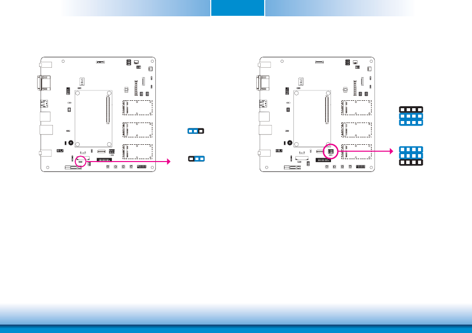
Clear CMOS Data
If you encounter the following situations,
a) CMOS data becomes corrupted.
b) You forgot the supervisor or user password.
you can reconfigure the system with the default values stored in the ROM BIOS.
To load the default values stored in the ROM BIOS, please follow the steps below:
1. Power-off the system and unplug the power cord.
2. Set JP6 pins 2 and 3 to On. Wait for a few seconds and set JP6 back to its default setting,
pins 1 and 2 On.
3. Now plug the power cord and power-on the system.
1-2 On: Normal
(default)
2-3 On:
Clear CMOS Data
Mini PCIe3 Signal Select
COM1
COM2
COM2
COM1
JP6
3
1 2
3
1 2
COM1
COM2
COM2
COM1
JP12
3
10
12
1
3
10
12
2-5-8-11, 3-6-9-12 On:
mSATA (default)
1-4-7-10, 2-5-8-11 On:
PCIe
The JP12 is used to select the Mini PCIe signal.
1