Chapter 2, Lcd/inverter power select, Bios select – DFI COM100-B User Manual
Page 13
Advertising
www.dfi .com
Chapter 2 Hardware Installation
13
Chapter 2
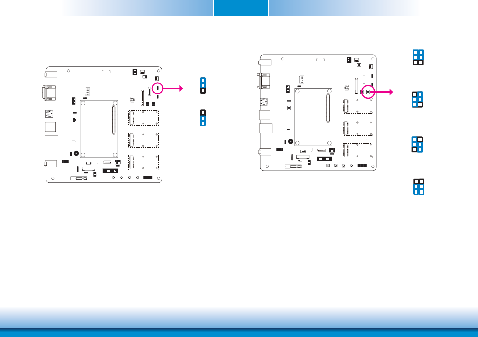
LCD/Inverter Power Select
COM1
COM2
COM2
COM1
JP18
1-2 On: +12V
2-3 On:
+5V (default)
3
1
2
3
1
2
The JP18 is used to select the power level of LCD inverter connector.
BIOS Select
The JP20 is used to determine the BIOS boot device.
JP20
1-2 On, 4-5 On:
Module SPI BIOS
COM1
COM2
COM2
COM1
3
1
2
4
5
6
2-3 On, 4-5 On:
NC
1-2 On, 5-6 On:
Carrier SPI0
2-3 On, 5-6 On:
Module SPI0 (default)
3
1
2
4
5
6
3
1
2
4
5
6
3
1
2
4
5
6
Advertising