EM Acoustics EMS-81 compact passive loudspeaker User Manual
Page 13
13
EMS Series User Manual
www.emacoustics.co.uk
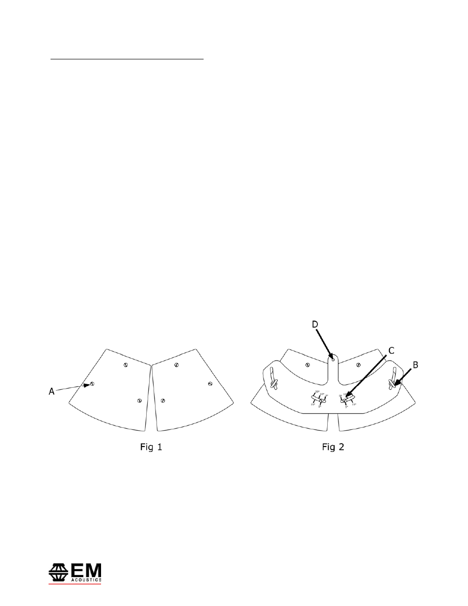
Attachment of the DFB-81 or DFB-121 flying bar
The EMS-121 enclosure is shown in the drawing, however the technique is the same for both the EMS-81 and EMS-
121 enclosures.
Position the two enclosures upright on a stable surface. Remove the M10 countersunk screws on the top of the
enclosure (marked “A” in Fig 1) on both enclosures. Position the DFB-121 above the enclosure, and fit M10 forged
shoulder eyebolts into the outer pair of mounting holes (marked “B” in Fig 2) and standard M10 hex-head set
screws into the inner pair of holes (marked “C” in Fig 2). Do not tighten these bolts until your array position is set
to the splay angle you require, indicated by the label on top of the plate. Once you have the desired angle, tighten
all bolts.
Carefully turn the cluster upside down, and repeat the above process. There is no need to fit eyebolts on the
underside of the enclosure.
Once your cluster is assembled, it can be suspended using steel cables or chains from the eyebolts. To set a
down-tilt angle, attach a shackle to the rear M12 hole on the lower DFB-121 (marked “D” in Fig 2), and utilise this
point to set the desired down-tilt. Assuming that this point is secured onto a solid structure, this down-tilt angle
point can be used as a secondary safety for the cluster. Alternatively, remove one of the countersunk M10 bolts
on the rear of the enclosures and fit another M10 eyebolt as a safety point.