ESI ESU1808 User Manual
Page 6
ESU1808
ESI
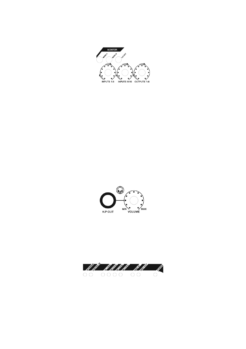
Monitor control section
This section allows you to control the monitoring with 3 independent gain knobs and 3 function
buttons.
INPUTS 1-8 controls the mixed level of all input signals from the front panel. INPUTS 9-16
controls the mixed level of all input signals from the rear panel. OUTPUTS 1-8 controls the mixed
level of all playback signals from your audio applications. The result is either sent out via the MIX
OUT outputs on the rear panel and / or the headphone output.
MONO A allows you to create a mono down mix for the signals from Input 1 & 2, MONO B
respectively creates a mono down mix for the signals from Input 3 & 4 in the monitoring signal.
The H.P OUT switch allows you to switch between monitoring the mixed signal via the headphone
output (enabled) or the signal from output channel 1/2 only (disabled).
A detailed description of monitoring signals with ESU1808 is provided in chapter 6.
Headphone Output
The headphone output is provided as a 1/4" phone connector labeled H.P OUT. The VOLUME
gain knob next to it controls the playback volume of it. The headphone output sends out the same
signal as the MIX OUT output on the rear panel if the H.P OUT switch (described earlier) is
enabled. If that switch is disabled, the headphone output sends out the playback signal from output
channel 1/2.
Status LEDs
Various LEDs on the front panel indicate the current operating status of ESU1808.
The INTERNAL LED shows if ESU1808 is currently generating the digital master clock internally,
while DIGITAL IN indicates that ESU1808 is synching itself to the S/PDIF digital input signal.
Next to that are the LEDs that are indicating the current sample rate. The supported rates are
44.1kHz, 48.0kHz, 88.2kHz and 96.0kHz.
6