6 grouting – Flowserve MP1 Sier-Bath User Manual
Page 17
MP1 USER INSTRUCTIONS ENGLISH 26999958
– 10-12
Page 17 of 48
flowserve.com
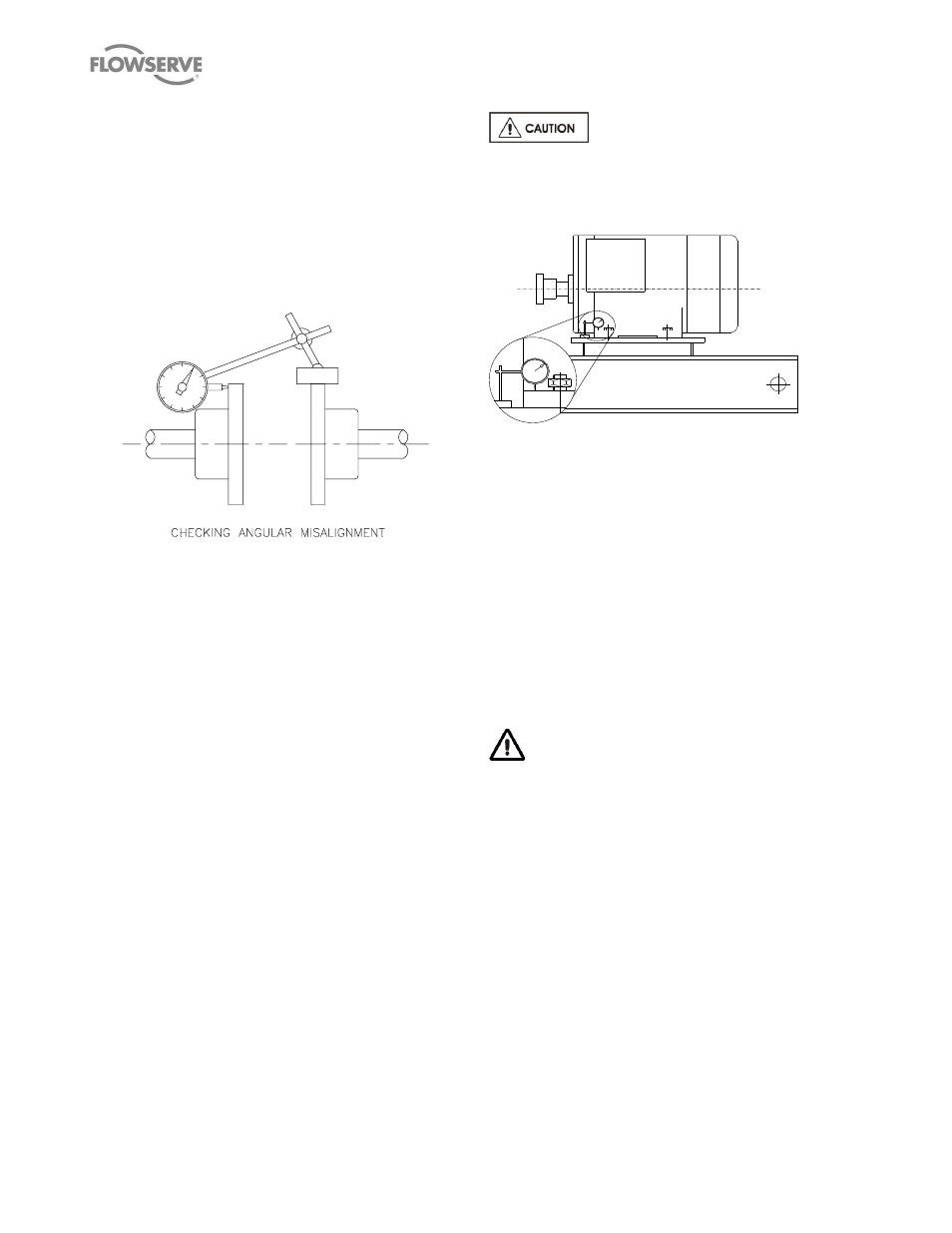
Angular Alignment:
With the magnetic base mounted on the pump half
coupling hub, move the dial indicator button to indicate
on the face of the driver half coupling hub as close to
the outside diameter as possible. (See Figure 4). Turn
both shafts 360
and record the dial readings at 90
intervals. Adjust the shims under the motor as required
and repeat the procedure until the angular alignment is
within 0.0005 mm (T.I.R.) per mm (0.0005 in. per in.)
of maximum hub diameter.
Figure 4
– Angular Misalignment
Repeat the checks on parallel and angular alignment,
ensuring the mounting bolts are secure, until the unit is
properly aligned. Note that correction in one direction
may affect the alignment in another direction. Re-
check the gap between the coupling hubs.
If any difficulty is encountered in achieving the
recommended alignment tolerances, the run out of the
pump and driver shafts and each coupling hub
diameter and face should be checked. Occasionally,
due to practical and unavoidable manufacturing
tolerance build-up associate with the pump, coupling
and driver, it may be necessary to match up the two
coupling hubs in the most advantageous relative
angular position in order to achieve an acceptable
alignment.
Do not install the coupling spacer or sleeve until
grouting is complete and cured and the alignment is
re-checked.
When the electric motor has sleeve bearings it is
necessary to ensure that the motor is aligned to run on
its magnetic centreline. A button (screwed into one of
the shaft ends) is normally fitted between the motor
and pump shaft ends to fix the axial position.
If the motor does not run in its magnetic
centre the resultant additional axial force may overload
the pump thrust bearing.
4.5.3 Check for soft foot
Figure 5
– Check for soft foot
This is a check to ensure that there is no undue stress
on the driver holding down bolts; due to non-level
baseplate or twisting. To check, remove all shims and
clean surfaces and tighten down driver to the
baseplate. Set a dial indicator as shown in Figure 5
and loosen off the holding down bolt while noting any
deflection reading on the dial test Indicator - a
maximum of 0.05 mm (0.002 in.) is considered
acceptable but any more will have to be corrected by
adding shims. For example, if the dial test indicator
shows the foot lifting 0.15 mm (0.006 in.) then this is
the thickness of shim to be placed under that foot.
Tighten down and repeat the same procedure on all
other feet until all are within tolerance.
Complete piping as below and see sections 4.9
Final shaft alignment check up to and including
section
5 COMMISSIONING, START-UP, OPERATION AND
SHUTDOWN before connecting driver and checking
actual rotation.
4.6 Grouting
The purpose of grouting is to provide rigid support to
the pump and driver by increasing the structural rigidity
of the baseplate and making it an integral mass with
the foundation.
Clean the roughed foundation surface and build a
wooden form around the baseplate (see Figure 1). For
initial grouting forms should be placed to isolate shims
and levelling nuts. The foundation surface should be
thoroughly saturated with water before grouting. A
typical mixture for grouting-in a pump base is
composed of one part pure Portland cement and two