Flowserve QLQ Vertical Worthington User Manual
Page 27
QLQ, QLQC USER INSTRUCTIONS ENGLISH 87900027 – 06/14
Page 27 of 61
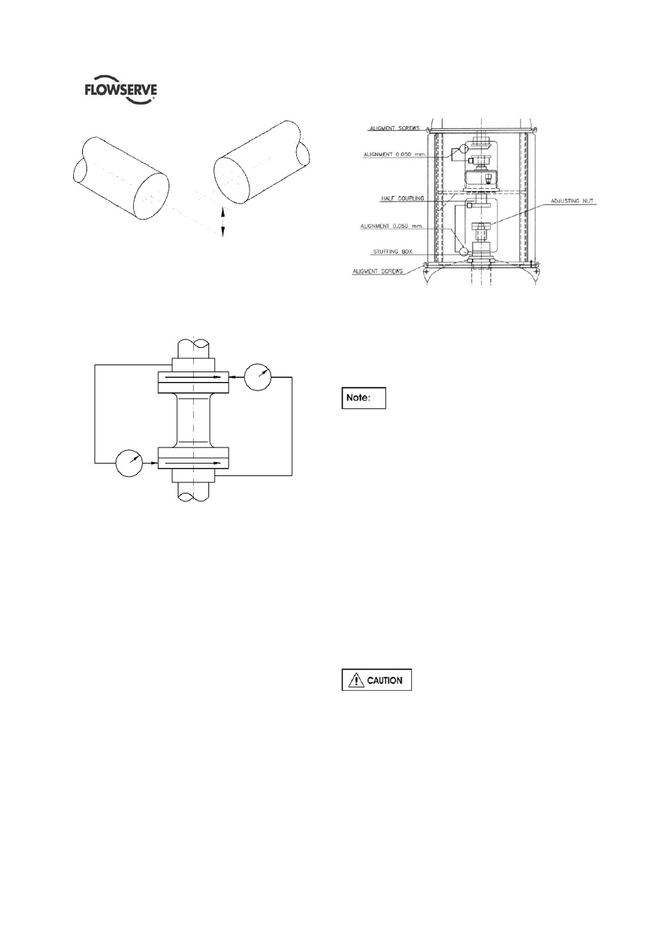
Figure 4.11 – combination of offset and angular misalignment
4.5.3.3 Alignment of flex coupling
For flexible couplings with narrow flanges use a dial
indicator as shown in figure 4.12 to check both
parallel and angular alignment.
For detailed alignment procedure refer to API RP686.
Figure 4.12
Maximum permissible misalignment at working
temperature:
Parallel 0.05 mm (0.002 in.) TIR
Angular
0.05mm/100mm
(0.0005In/In)
4.5.3.4 Alignment of rigid coupling
Place the indicator of the machined surface of the
stuffing box.
If the pump is equipped with a packing seal, a 2-
halved ring is provided to be inserted in the stuffing
box to keep the shaft centered in the correct position
Figure 4.13
Maximum permissible misalignment at working
temperature:
Parallel 0.05 mm (0.002 in.) TIR
Angular
0.05mm/100mm
(0.0005In/In)
a) Pumps with thick flanged non-spacer couplings
can be aligned by using a straight-edge across
the outside diameters of the coupling hubs and
measuring the gap between the machined faces
using feeler gauges, measuring wedge or
calipers.
b) When the electric motor has sleeve bearings, it is
necessary to ensure that the motor is aligned to
run on its magnetic centerline.
c) Refer also to section 4.1.6 for alignment of
pumps with both mechanical seal and thrust
bearing.
Refer to the motor User Instructions for details.
A button (screwed into one of the shaft ends) is
normally fitted between the motor and pump shaft
ends to fix the axial position.
If the motor does not run in its
magnetic center the resultant additional axial force
may overload the pump thrust bearing.
If the pump is handling hot liquid, the alignment must
be rechecked in warm condition of the unit. The
alignment of the unit shall be checked again after 200
service hours.