10 sealing arrangements – Flowserve WR User Manual
Page 19
WR and CR USER INSTRUCTIONS ENGLISH 26999968 10-12
Page 19 of 28
flowserve.com
6.9.1 Wear ring clearances
Pump
size
Impeller hub
diameter (mm)
Diametral ring or casing
clearance (mm)
Front
Back
Front
Back
25-161
55.54/55.47
55.54/55.47
0.60/0.46
0.60/0.46
32-125
70.54/70.47
70.75/70.47
0.60/0.46
0.60/0.46
32-160
32-200
40-200
82.54/82.45
82.54/82.45
0.64/0.46
0.64/0.46
40-250
50-125
50-160
65-100
50-200
93.54/93.45
93.54/93.45
0.64/0.46
0.64/0.46
50-250
50-315
65-125
65-160
80-125
111.47/111.38
93.54/93.45
0.71/0.53
0.64/0.46
65-200
111.47/111.38
111.47/111.38
0.71/0.53
0.71/0.53
65-250
65-315
80-160
100-160
152.47/152.37 152.47/152.37
0.67/0.53
0.67/0.53
100-200
100-250
100-315
100-400
125-250
125-315
125-225
168.10/168.00 168.10/168.00
0.80/0.60
0.80/0.63
125-400
184.00/183.90 184.00/183.90
0.71/0.53
0.71/0.53
150-250
209.40/209.30 209.40/209.30
0.80/0.60
0.80/0.63
150-315
150-400
150-500
219.47/219.37 219.47/219.37
0.73/0.53
0.73/0.53
200-401
269.24/269.14 269.24/269.14
0.85/0.65
0.85/0.65
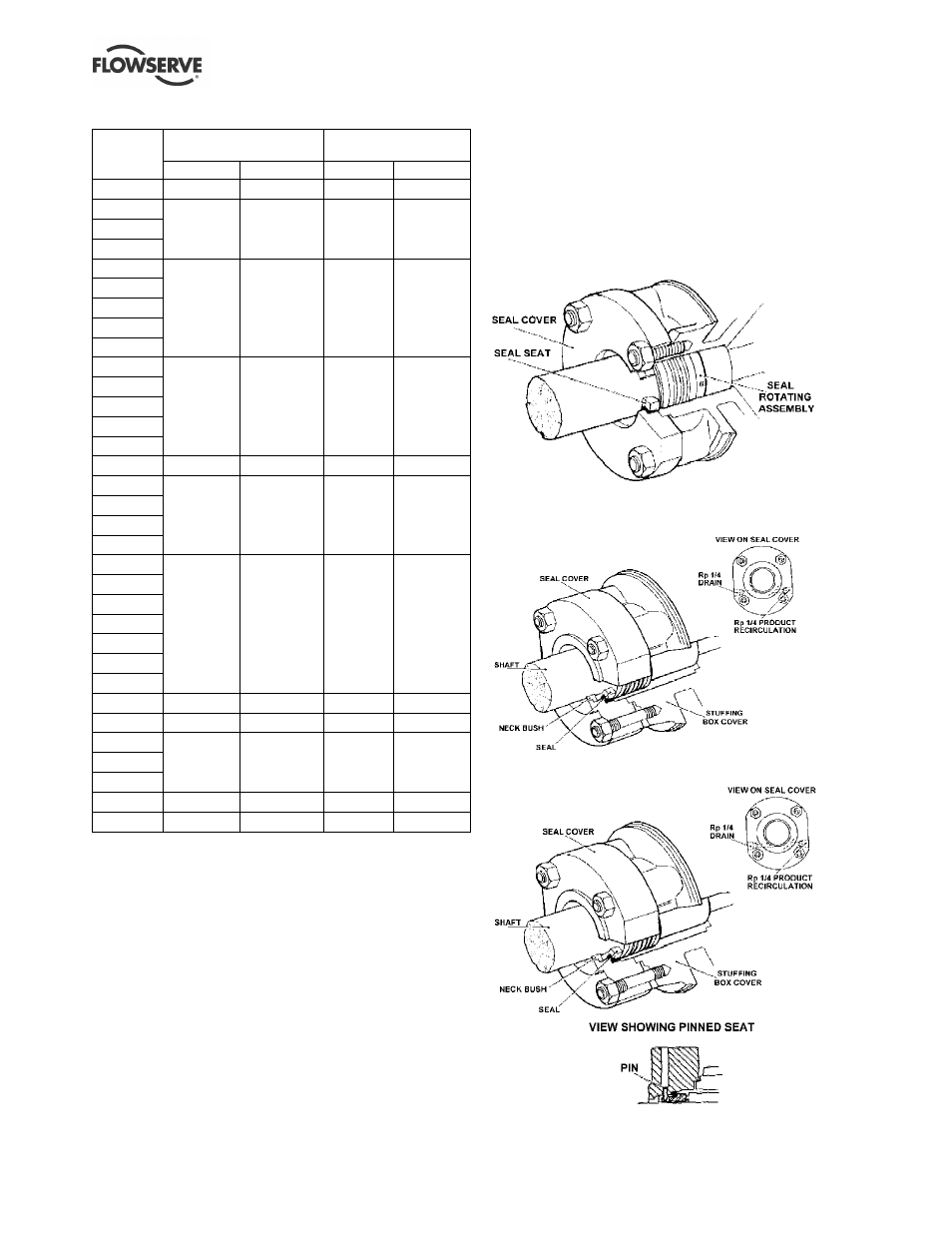
6.10 Sealing arrangements
This section shows details of the seal arrangements.
Contact your nearest Flowserve sales office or service
centre if you require further information or are unsure
of the specific arrangement supplied.
6.10.1 Single seal types
6.10.1.1 Single seal with simple seal cover
6.10.1.2 Single seal arranged for recirculation
from discharge (API plan 11)
6.10.1.3 Single seal with external PTFE neck bush