3 impeller clearance, 4 direction of rotation – Flowserve S-series PolyChem User Manual
Page 26
USER INSTRUCTIONS POLYCHEM S-SERIES ENGLISH 71569207 11-08
Page 26 of 52
flowserve.com
5.2.2 Grease
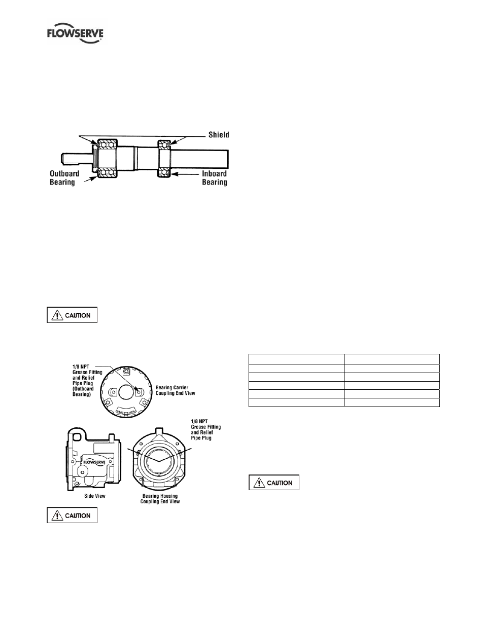
5.2.2.1 Regreasable single shielded bearings
When the grease lubrication option is specified,
single shielded bearings, grease fittings and vent pipe
plugs are installed inboard and outboard.
Figure 5-8: Pump shield orientation
The bearings are packed with MOBIL POLYREX EM
grease prior to assembly. The grease reservoir should
be packed prior to operating the pump in accordance
with the relubrication instructions. For relubrication, a
grease with the same type base (polyurea) and oil
(mineral) should be used. To regrease, remove the
pipe plug from both the inboard and outboard bearing
location. (See Figure 5-9.) Add grease through each
fitting until either grease is expelled out the purge hole
or until the required volume of grease has been added.
(See Figure 5-6.) After relubricating the bearings three
times, it is typically recommended that the bearing
housing is cleaned out.
To regrease bearings under coupling
guard, stop pump, lock the motor, remove coupling
guard, and then regrease the bearings.
Figure 5-9: Regreasable configuration
Do not fill the housing with oil when
greased bearings are used. The oil will leach the
grease out of the bearings and the life of the bearings
may be drastically reduced.
5.2.2.2 Grease for life - double shielded or double
sealed bearings
These bearings are packed with grease by the
bearing manufacturer and should not be relubricated.
The replacement interval for these bearings is greatly
affected by their operating temperature and speed.
Shielded bearings typically operate cooler.
5.2.3 Oil mist
The inlet port for all horizontal pumps is the plugged
½ in. NPT located at the top of the bearing housing. A
vent fitting has been supplied on the bearing carrier as
well as a plugged ¼ in. NPT bottom drain on the
bearing housing. See section 4.6.6.4, Piping
connection - Oil mist lubrication system. Do not allow oil
level to remain above the center of the bearing housing
sight glass window with purge mist (wet sump) systems.
The optional oil slinger must not be used with an oil
mist system.
5.3 Impeller clearance
The impeller clearance was set at the factory. For
open impellers the clearance is based on the
application temperature at the time the pump was
purchased. (See Figure 5-10.) If the process
temperature changes the impeller clearance must be
reset. All open style impellers are set to the casing.
The preferred setting for a closed style impeller is
midway between the casing and the cover. See
section 6.6 for impeller adjustment instructions.
Figure 5-10: Open impeller clearance settings
Temperature °C (°F)
Clearance mm (in.)
< 38 (100)
0.58 ± 0.08 (0.023 ± 0.003)
38 to 65 (101 to 150)
0.71 (0.028)
66 to 93 (151 to 200)
0.84 (0.033)
94 to 121 (201 to 250)
0.97 (0.038)
122 to 149 (251 to 300)
1.09 (0.043)
Notes.
1. Rotation of bearing carrier from center of one lug to center of
next results in axial shaft movement of 0.1 mm (0.004 in.).
2. Open impellers are set to casing.
5.4 Direction of rotation
5.4.1 Rotation check
It is absolutely essential that the
rotation of the motor be checked before connecting
the shaft coupling. Incorrect rotation of the pump, for
even a short time, can dislodge and damage the
impeller, casing, shaft and shaft seal. All PolyChem
S-series pumps turn clockwise as viewed from the
motor end. A direction arrow is cast on the front of
the casing as shown in Figure 5-11. Make sure the
motor rotates in the same direction.