1equipment check – Flowserve XLC Series User Manual
Page 2
2
1
Equipment Check
1.1 Follow plant safety regulations prior to equipment disassembly:
• Lock out motor.
• Wear designated personal safety equipment.
• Consult plant MSDS files for hazardous material regulations.
1.2 At the first installation of an XLC bearing disassemble fan shaft assembly
in accordance with equipment manufacturer’s instructions and remove
upper bearing arrangement. Retain upper bearing mounting bolts and/or
nuts for XLC bearing installation.
1.3 Check bearing assembly drawing for any modifications required to the
equipment before installation and act accordingly.
1.4 Check shaft OD, distance to the first obstruction, and bearing housing
bolting to ensure they are dimensionally within the tolerances shown on
the bearing assembly drawing. Check bolt length to ensure adequate
thread engagement for the actual bearing housing.
1.5 Thoroughly inspect and clean the mounting plate and shaft or shaft
sleeve. Inspect for corrosion or any defects. Remove all burrs, nicks or
scratches, and sharp edges from the shaft and/or sleeve in the bearing
area. Remove sharp edges from keyways and threads. Replace worn
shaft or shaft sleeve.
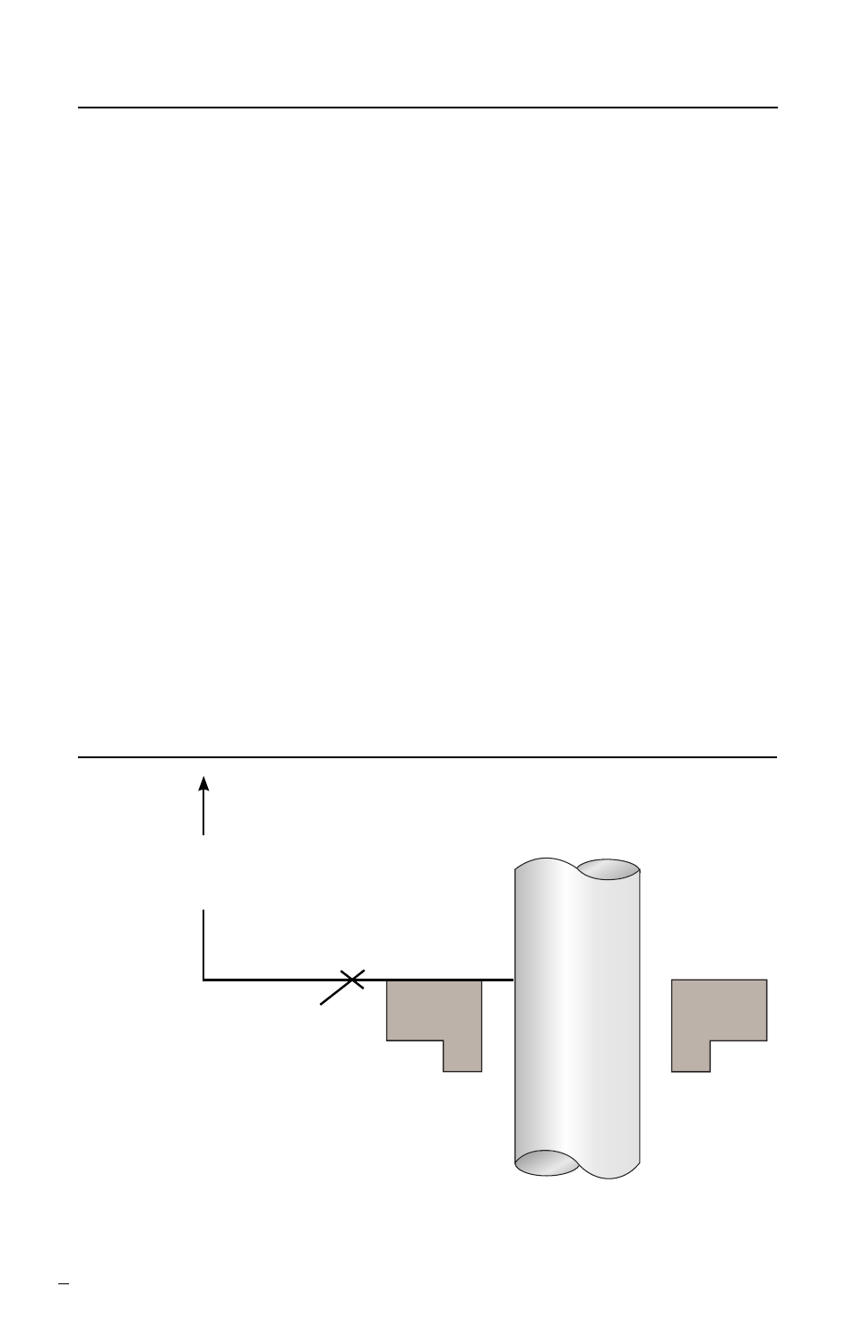
1.6 Check equipment requirements as described in Figure 1. Any reading
greater than what is allowed must be brought within specifications.
Mounting Requirements
Figure 1
102 mm (4.0 inch)
to first obstruction
Sleeve or shaft finish to be
0.4 mmm (16 minch) R
a
or better
Face of mounting plate to be square
to the axis of the shaft within
2.5° of perpendicular
• Maximum shaft runout at mounting plaste = 0.05 mm (0.002 inch) FIM
• Maximum dynamic shaft deflection at mounting plate = 0.05 mm (0.002 inch) FIM
Shaft or sleeve OD
+0.000 mm (+0.000 inch)
-0.050 mm ( -0.002 inch)