Flowserve 1400 Valtek Logix User Manual
Page 9
46-9
Flowserve Corporation, Valtek Control Products, Tel. USA 801 489 8611
LED Indicators
The Logix 1400 digital positioner has three LED indica-
tors that are visible through a window in the main cover.
Only one LED will blink at any given time. Each LED has
a different color to convey basic information about the
positioner status. Green indicates that the positioner is
operating normally. Yellow indicates that a ‘customer
defined limit’ or ‘alert’ has been reached. Red indicates
that an error condition exists. A fieldbus configurator
must be used to determine the specific reason for a
yellow or red LED status.
During stroke and actuator calibration, no LED will blink.
After calibration is complete, the green LED indicates
that the calibration was completed successfully. If the
yellow or red LED blinks after a calibration process, a
warning or error was detected and the configurator must
be used to identify the specific calibration error.
NOTE: If the LED indicator changes from green to yellow
after a calibration process, the user may have set a
warning limit (position alert, cycle counter alert, etc.).
Use a fieldbus configurator to monitor status.
Re-Cal Button
If the fieldbus configurator is not available, Logix 1400
digital positioner has a Re-Cal feature that performs a
stroke calibration and allows basic operation of the positioner.
NOTE: The Re-Cal operation retains all previously config-
ured information. All settings remain unchanged except
stroke calibration parameters. If the device is being
installed for the first time, factory default parameters are
used. The FB Configurator must be used the first time to
configure the Logix 1400 digital positioner. The trans-
ducer block must be out of service for Re-cal to work.
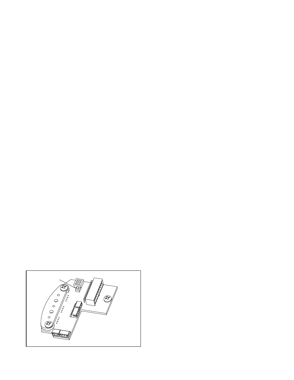
The Re-Cal button is located on the collector board inside
the main housing chamber as shown in Figure 10.
Warning: Accessing this function requires removal
of the main cover. The user must take all necessary
precautions if this operation is performed in explo-
sion-proof areas.
Make the appropriate configuration settings, using FB
Configurator and CONTROL_FLAGS variable. ATO/ATC
selects air-to-open or air-to-close (this is determined by
the mechanical tubing of the actuator). The Actuator
Style check box allows the user to select linear or rotary
feedback linkage. If
Custom is selected, the positioner
activates custom characterization.
Press Re-Cal button and hold for five seconds. If the button
is released before five seconds have elapsed, no action
will be taken. After five seconds, the positioner will begin
a stroke calibration. Release the Re-Cal button once
calibration has started. The positioner will automatically
stroke the valve. No LED will blink during this process.
Upon completion of calibration:
• A blinking green LED indicates the valve is in control
mode and calibration was successful.
• A blinking yellow LED immediately after a stroke
calibration usually indicates that the valve did not
stroke. Check the air supply and cable connections.
• The red LED will blink if a calibration error occurred.
The cause of a red LED is generally a stem position
linkage/feedback sensor alignment problem. For
linear linkage, the active electrical feedback angle is
65 degrees. For rotary linkage, the active electrical
feedback angle is 95 degrees. The red LED indicates
that the mechanical travel is not centered within the
electrical sensor travel. If a red LED is blinking after
a stroke calibration, loosen the feedback sensor
mounting screws as shown in Figure 9. Turn the stem
position sensor slowly while watching the LED indica-
tors. Try small movements, both clockwise and counter-
clockwise. If the yellow LED begins to blink, the
feedback sensor has been correctly moved into range.
Tighten the feedback sensor mounting screws and
repeat the Re-Cal procedure. If the LED remains red
even after moving the full length of the sensor slot,
verify the following items:
Rotary check box setting
under the CONTROL_FLAGS parameter ‘Actuator
Style’ (checked is rotary, unchecked is linear), stem
clamp and take-off arm height.
NOTE: If the stroke stops in the closed position, the error
occurred when the position sensor/linkage was at closed
position. If the stroke stops in the open position, the error
occurred when position sensor/linkage was at the open
position. No calibration parameters are saved if an error
occurs. If the power to the positioner is removed, the unit
will power-up with the previous configuration parameters.
A successful calibration will save parameters.
If the valve does not stroke after pressing the Re-Cal
button, this may be an indication that the internal regu-
lator pressure and/or the driver module minimum pres-
sure is low. Refer to the following instructions to check
and set the internal regulator and minimum pressure
settings.
Note that the tools and equipment used in the next two
procedures are from indicated vendors.
Figure 10: Re-Cal Button
Re-Cal Button
NOTE: DIP switches not
used on Logix 1400
positioner