Flowserve Valtek Beta Positioners for Control Valves User Manual
Page 6
24-6
Flowserve Corporation, Valtek Control Products, Tel. USA 801 489 8611
Figure 9: Installation for Cam Return Spring
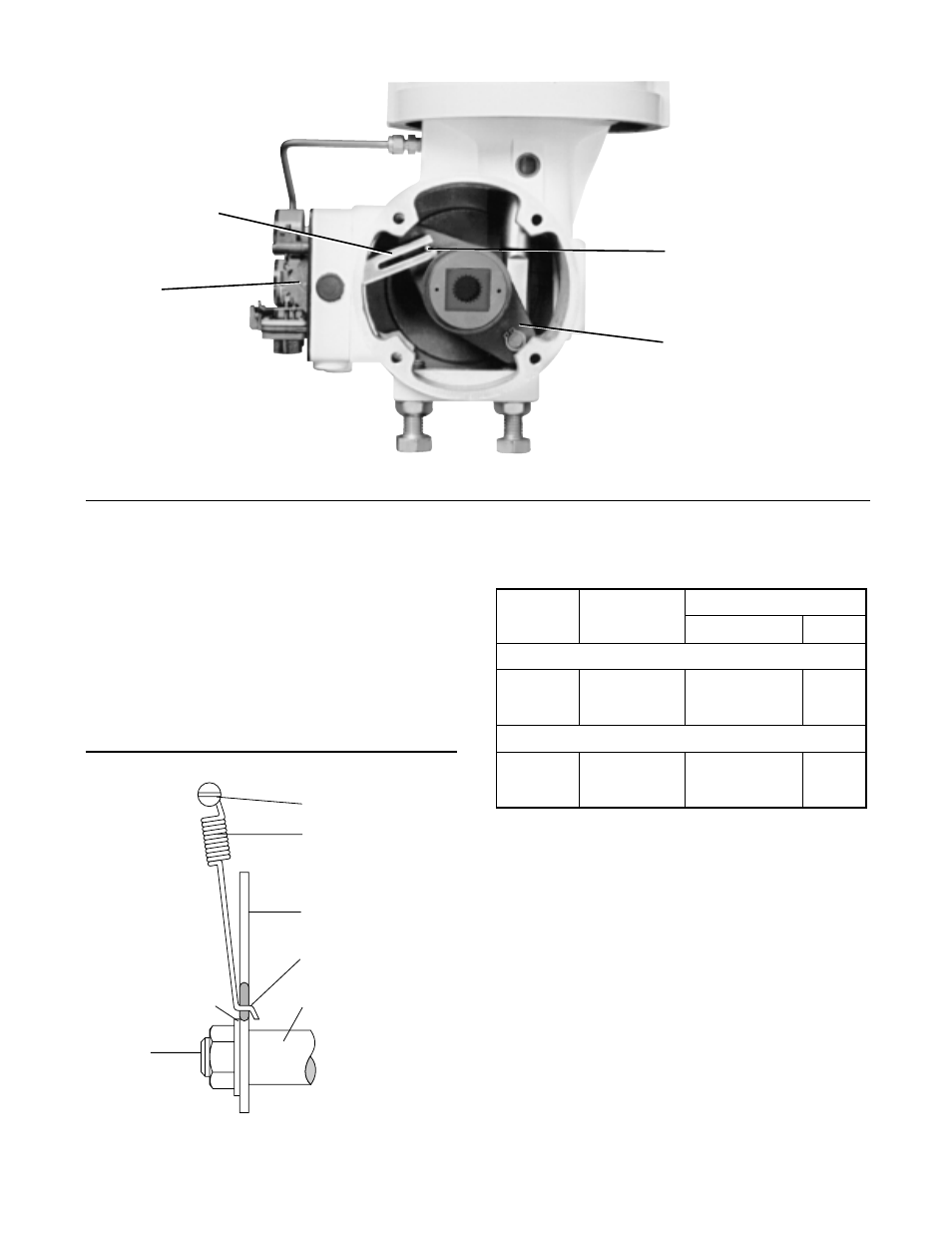
Figure 8: Beta Positioner Installation on Rotary Actuator
Installing Positioner on Rotary Actuators
Proceed as follows when installing the Beta positioner
on all sizes of rotary actuators if the cam and follower
arm are not already installed, otherwise refer directly to
step 7.
1. Remove the feedback spring (34) and rotate the
zero adjustment arm (22) out of the way. Remove
the snap ring (8) from the range adjustment arm
post and remove the range adjustment arm (13).
2. With the desired cam (see Table 1) and its identifi-
cation letter facing towards the cam shaft, slide the
cam (56) onto the end of the cam shaft having the
shorter shoulder (57). (Refer to Table 1 to deter-
mine desired cam characteristic). Fasten with the
star lock washer (32) and nut (33).
3. Insert the follower arm (58) into the back recess of
the positioner with part identification number facing
out. Slide the cam shaft (57) through the inner
bearing and then slip the flatted hole of the follower
arm (58) over the longer stepped shoulder of the
cam shaft (57).
4. Place a small amount of threadlocking compound
(Loctite #222 or equivalent) to the threaded portion
Screw
Return Spring
Cam
Grease Here
Cam Shaft
Lock Washer
Nut
Follower Pin
Actuator Lever Arm
Follower Arm
Cam
Table I: Rotary Actuator
Cam Characteristic Chart
Cam
Fail
No.
Action
Valdisk and ShearStream
10036583
Air-to-Open
B
C
10036583
Air-to-Close
C
B
MaxFlo
10004481
Air-to-Open
B
C
10099732
Air-to-Close
B
C
(1) Letters are the markings stamped on either side of the cam.
Equal Percent Linear
Characteristic
(1)